Dual channel downconverter for pulsed radio frequency measurements

a technology of pulsed radio frequency and downconverter, which is applied in the direction of transmission, transmission noise suppression, electrical equipment, etc., can solve the problems of insufficient conversion of input and output rf signals, inability to accurately and repeatably measure pulsed two-port rf device parameters with sub-microsecond pulse width, and increasing complexity of measurement task, etc., to achieve accurate and repeatable measurement, good dynamic range, and reduced measurement time

Inactive Publication Date: 2006-06-06
THE UNITED STATES OF AMERICA AS REPRESENTED BY THE SECRETARY OF THE NAVY
View PDF14 Cites 14 Cited by
  • Summary
  • Abstract
  • Description
  • Claims
  • Application Information

AI Technical Summary

Benefits of technology

[0021]Another object of the present invention to provide a dual channel downconverter that provides for decreased measurement time, thereby allowing high frequency pulses to be measured accurately and repeatably with good dynamic range.
[0022]Yet another object of the present invention is to provide a dual channel downconverter that possesses a simple design incorporating durable, commercially available components / devices.
[0023]It is another object of the present invention to provide a dual channel downconverter that may be economically produced to provide for widespread use.
[0024]These and other objects are accomplished by a dual channel downconverter possessing a simple design, incorporating durable, commercially available components / devices, that may be economically produced to provide for widespread use. That design includes a two-channel heterodyne receiver architecture (i.e. two separate and distinct downconverting signal channels) that downconverts two frequency-agile, pulsed RF signals to identical fixed IF signals without the use of a tunable local oscillator. The present invention accomplishes the downconversion while preserving, in the IF output signals, any amplitude modulations present in the RF signals. The present invention also preserves phase difference changes present in the RF signals while rejecting the phase modulations common to those input signals. The present invention has two RF input ports and two, corresponding IF output ports and facilitates the complex response measurements of pulsed two-port RF devices while operating in a target system such as a radar transmitter. When used for a complex response measurement of this type, the present invention's IF outputs can be digitized and processed to obtain insertion gain, insertion phase, residual phase noise, error vector magnitude, AM noise, and group delay. IF measurement techniques incorporating the present invention provide for decreased measurement time, thereby allowing high frequency (i.e. sub-microsecond) pulses to be measured accurately and repeatably with good dynamic range. Additional novel features of the present invention include:

Problems solved by technology

The task of measuring pulsed two-port RF device parameters with sub-microsecond pulse widths is growing more complex.
Unfortunately, this device is intended for simultaneous processing of two oppositely polarized satellite broadcasting / communication signals and is, therefore, wholly inadequate for converting the input and output RF signals of a pulsed two-port RF device into fixed IF signals while preserving the relative amplitude and phase of the RF signals.
Unfortunately, as with the Kashima et al. device above, these dual channel downconverters were intended for use in the simultaneous processing of two oppositely polarized television signals and cannot be used to convert the input and output RF signals of a pulsed two-port RF device into fixed IF signals.
Unfortunately, this two-band device was conceived merely to increase the bandwidth capability of downconverters.
Unfortunately, this mathematical method / algorithm requires a local oscillator and fails to provide amplitude and phase measurements.
Unfortunately, this device is merely a vector network analyzer that includes a local oscillator.
Unfortunately, once again, this mathematical method / algorithm requires a local oscillator and fails to provide amplitude and phase measurements.
Unfortunately, this measurement apparatus provides only frequency data.
Current techniques for measuring the complex response (i.e. amplitude and phase) of a pulsed two-port RF device (e.g. an amplifier) involve complicated and expensive test instruments.
However, a pulsed VNA has inherent limitations when used to measure the complex response of a pulsed two-port device that is a subcomponent of a radar transmitter.
Thus, while the concepts of dual channel downconverters and pulsed RF signal measurement devices are fairly well-known, none of the foregoing apparatus / methods comprise a dual channel downconverter without an associated local oscillator that is specifically intended for measuring and analyzing the complex response (i.e. amplitude and phase data) of pulsed RF signals.
It becomes difficult to use a VNA when analyzing a pulsed two-port RF device in a radar transmitter where the stimulus to the DUT is a complex pulsed waveform with frequency tuning and modulation of the RF carrier.
This RF stimulus to the DUT is usually already present and it would be undesirable to replace it with the VNA's stimulus.
It is equally impractical for the VNA to maintain a fixed IF in the VNA's downconverter because complex frequency tuning and modulation of the VNA's LO is required.

Method used


Image

  • Dual channel downconverter for pulsed radio frequency measurements
  • Dual channel downconverter for pulsed radio frequency measurements
  • Dual channel downconverter for pulsed radio frequency measurements

Examples


Embodiment Construction

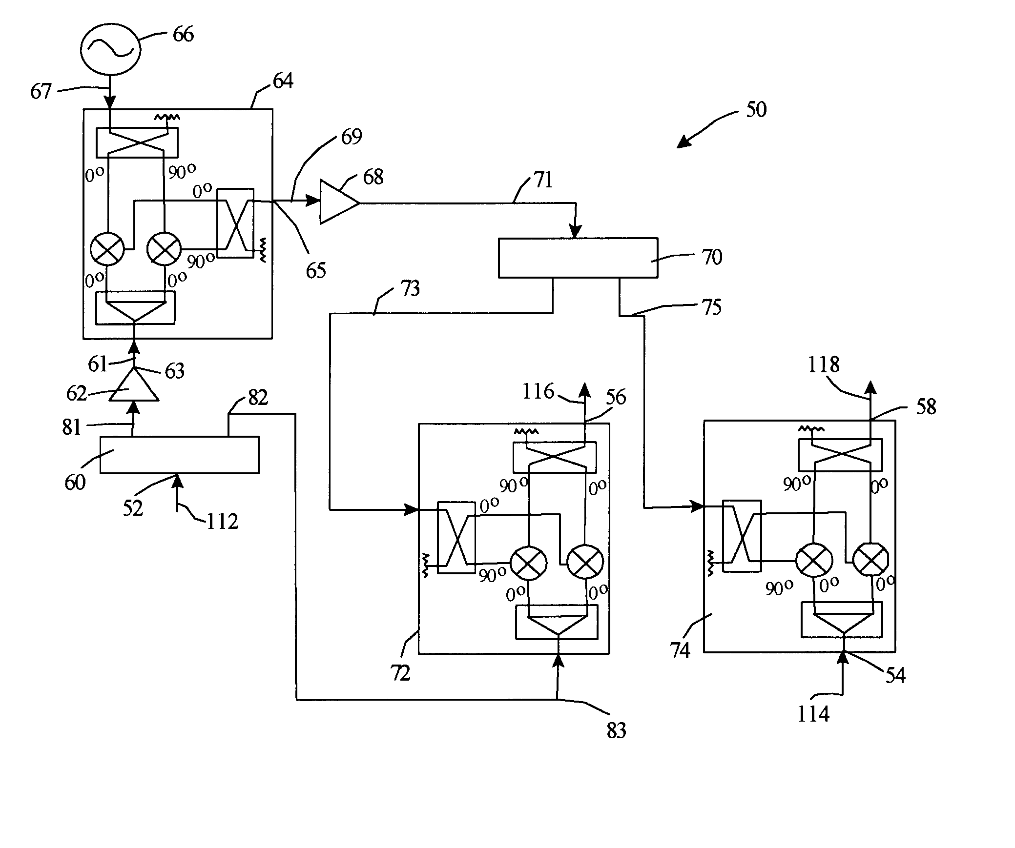
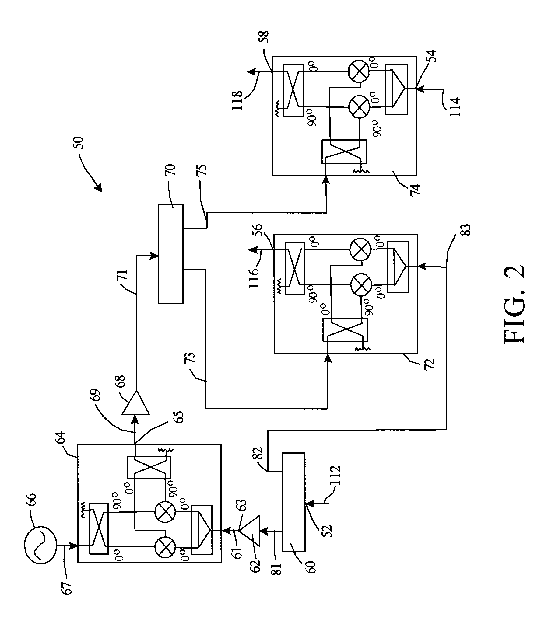
[0032]FIG. 2 is a schematic representation of a dual channel downconverter 50 according to a preferred embodiment of the present invention. FIG. 3 provides a schematic representation of the dual channel downconverter 50 as used in a complex response measurement system 100.

[0033]The dual channel downconverter 50 incorporates the architecture of a two-channel heterodyne receiver that downconverts two frequency-agile, pulsed RF signals 112, 114 to fixed IF signals 116, 118 without the use of an expensive tunable local oscillator (“LO”). The present dual channel downconverter 50 has two RF input ports 52, 54, and two corresponding downconverted IF output ports 56 and 58. A sample of the RF signal 112 incident upon the two-port DUT 110 is input to port 52 and a sample of the RF signal 114 transmitted through the DUT 110 is input at port 54.

[0034]The RF signal 112 input at port 52 is split into two paths 81, 82 by a power divider 60. One output 81 of the power divider 60 is used for the g...


PUM


Abstract

A dual channel downconverter that includes a two-channel heterodyne receiver architecture for downconverting two frequency-agile, pulsed RF signals to identical fixed IF signals without the use of a tunable local oscillator. This accomplishes downconversion while preserving, in the IF output signals, any amplitude modulations present in the RF signals. The device also preserves phase difference changes present in the RF signals while rejecting the phase modulations common to those input signals. The present device facilitates complex response measurements of pulsed two-port RF devices while operating in a target system such as a radar transmitter, including insertion gain, insertion phase, residual phase noise, error vector magnitude, AM noise, and group delay, all with increased accuracy, good repeatability, good dynamic range, and decreased measurement time.

Description

STATEMENT OF GOVERNMENT INTEREST[0001]The invention described herein may be manufactured and used by or for the Government of the United States of America for governmental purposes without payment of any royalties thereon or therefor.BACKGROUND OF THE INVENTION[0002]1. Field of the Invention[0003]The present invention relates to the measurement of pulsed radio frequency (RF) devices and, more particularly, to the conversion of pulsed RF signals into fixed intermediate frequency (IF) signals and, even more particularly, to a dual channel downconverter for automatically converting the input and output RF signals of a pulsed two-port RF device into fixed IF signals while preserving the relative amplitude and phase of the RF signals.[0004]2. Description of the Background[0005]The task of measuring pulsed two-port RF device parameters with sub-microsecond pulse widths is growing more complex. Simultaneously, the need for test, or measurement, systems combining improved accuracy with redu...

Claims


Application Information

Patent Timeline
Patent Type & Authority Patents(United States)
IPC IPC(8): H04B1/16
CPCH04B1/28
Inventor MITSDARFFER, KENNETH BRYANHOOVER, LOWELL ROYTHELEN, DEAN
Owner THE UNITED STATES OF AMERICA AS REPRESENTED BY THE SECRETARY OF THE NAVY
Why Eureka
Try Eureka