
Hydraulic system for a motor vehicle

a technology for motor vehicles and hydraulic systems, applied in hydraulic systems, rotary clutches, braking systems, etc., can solve problems such as wear properties of master cylinders, and achieve the effect of less prone to abrasive wear

Inactive Publication Date: 2006-06-13
LUK LAMELLEN & KUPPLUNGSBAU BETEILIGUNGS KG
View PDF15 Cites 10 Cited by
  • Summary
  • Abstract
  • Description
  • Claims
  • Application Information

AI Technical Summary

Benefits of technology

[0003]The objective of the present invention is to provide a hydraulic system that is less prone to abrasive wear.
[0006]The piston may in addition contain PTFE (polytetrafluoroethylene) and / or molybdenum disulfide (MoS2) and / or graphite. Combinations containing these materials result in optimal wear properties of the master cylinder.
[0009]In a further developed version of a hydraulic system according to the invention, the housing may in addition contain PTFE. This leads to a further improvement in the gliding properties of the piston inside the housing and contributes further to preventing the abrasion of surface material.
[0010]In a preferred embodiment of the hydraulic system, the surface of the piston has a surface finish with an average surface roughness value between about 0.1 μm and about 2 μm, preferably around 0.3 μm. The surface of the piston may have a maximum-depth roughness value in the range between about 1 μm and about 10 μm, preferably around 4.5 μm. The surface of the piston may have a bearing ratio of about 30% to 80%. Experiments have shown that a surface according to the foregoing specifications provides optimal results in pistons and housings with the material combinations according to the invention.
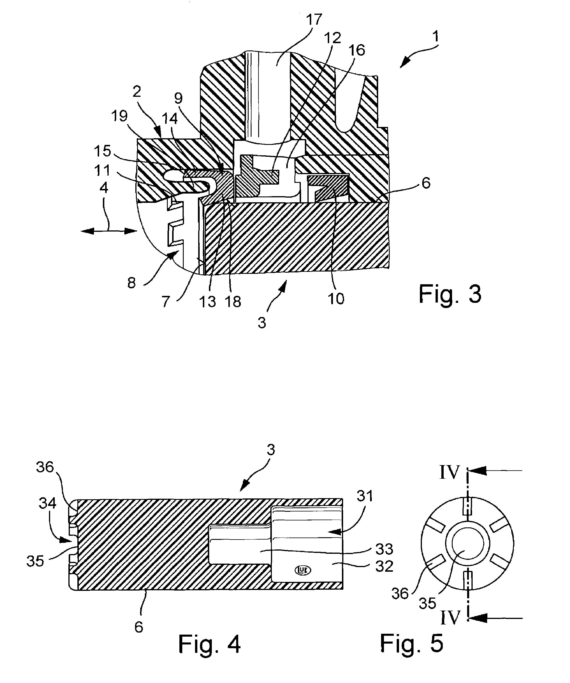
[0011]In a preferred embodiment of the hydraulic system according to the invention, the piston has at least one snifting groove arranged preferably on the axially facing front side of the piston. In comparison to an arrangement of the snifting grooves on the circumference of the piston, the arrangement on the end surface improves the snifting play and the dynamic snifting properties. The piston has preferably several snifting grooves distributed over the perimeter of the axially facing piston surface. The snifting grooves can be distributed evenly or unevenly over the perimeter. The depth of a snifting groove is about 0.5 to 1.5 mm, measured from the axially facing surface of the piston. This geometry of the snifting grooves results in optimal self-venting and snifting properties.

Problems solved by technology

Combinations containing these materials result in optimal wear properties of the master cylinder.

Method used


Image

  • Hydraulic system for a motor vehicle
  • Hydraulic system for a motor vehicle
  • Hydraulic system for a motor vehicle

Examples


Embodiment Construction

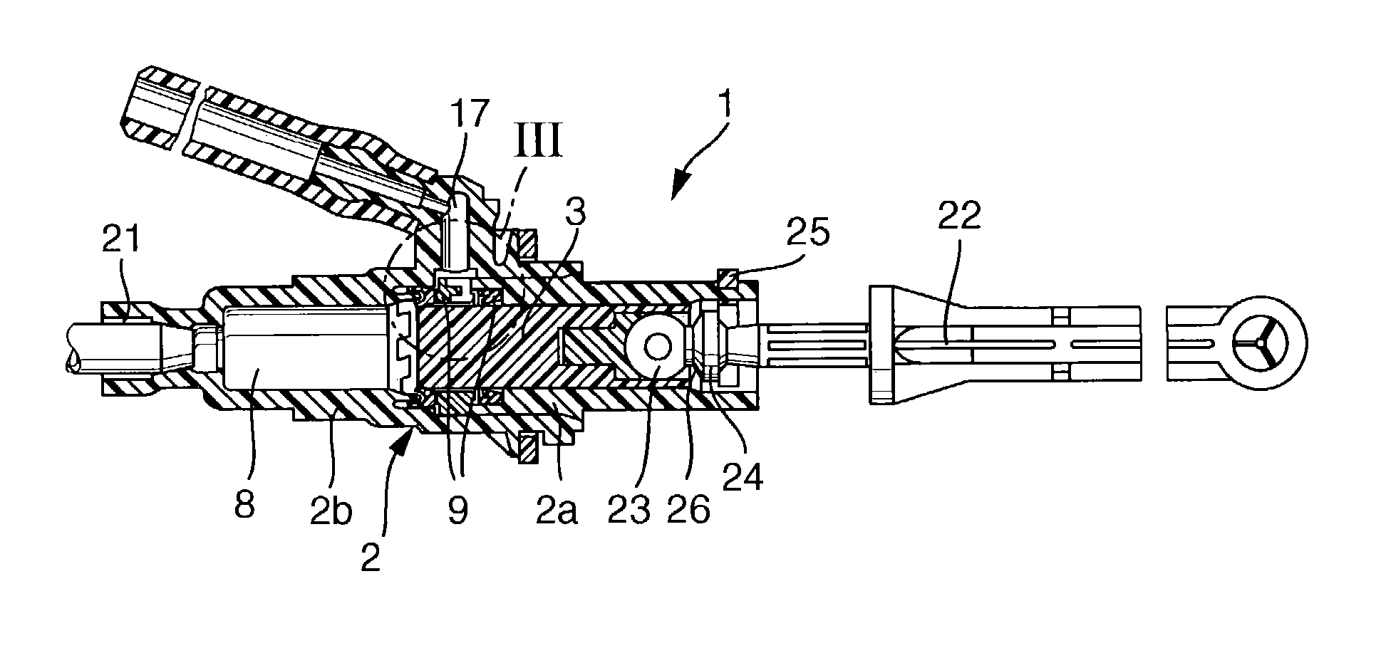
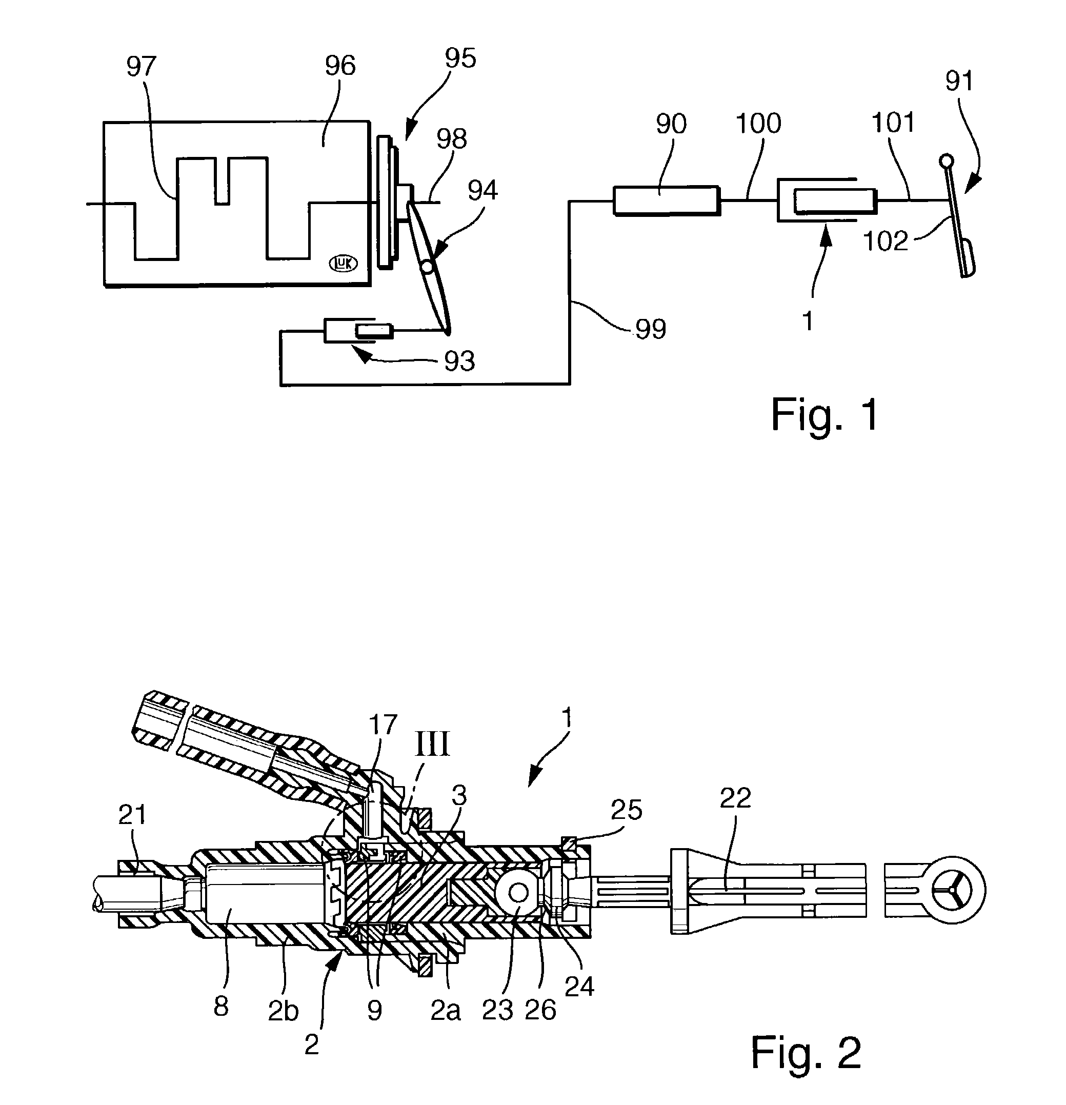
[0020]FIG. 1 schematically illustrates a possible configuration of a hydraulic system with a pressure-limiting valve 90 as used in a clutch release device 91 with a master cylinder 1 and a slave cylinder 93. The pressure-limiting valve 90 in the illustrated example is installed between the conduit sections 99 and 100, which are separated from each other in the closed state of the valve. Obviously, in different embodiments the pressure-limiting valve 90 could be integrated in the master cylinder 1 or in the slave cylinder 93. In other hydraulic systems such as brake systems, power-steering systems and the like, the pressure-limiting valve could be integrated in a functional component of the system. A pressure-limiting valve according to the invention can be used to advantage in any hydraulic system as a pressure-limiting device and / or as an oscillation filter, e.g., to prevent pedal vibrations.

[0021]The clutch release system 91 performs a hydraulic clutch-pedal actuation when a force...


PUM


Abstract

The piston in the master cylinder of a hydraulic system of the kind that is used particularly in motor vehicles is made of a duroplastic polymer material.

Description

BACKGROUND OF THE INVENTION[0001]The present invention relates to a hydraulic system of the kind that is used particularly in motor vehicles, which has a master cylinder with a housing and a piston arranged with axial mobility in the housing. The piston closes off a pressure compartment filled with a hydraulic fluid. When the master cylinder is actuated, the piston is moved by means of a piston rod and as a result, a pressure is applied to the hydraulic fluid. At least one sealing means is arranged between the housing and the piston. The hydraulic system further has a slave cylinder that is connected into the system through a pressure conduit.[0002]A hydraulic system that meets the foregoing description is known for example from DE 100 49 913 A1. In particular in a case where polymer materials are used for the housing and / or piston, this hydraulic system suffers from a problem that is due to transverse forces acting on the piston as a result of swivel movements of the piston. The tr...

Claims


Application Information

Patent Timeline
Patent Type & Authority Patents(United States)
IPC IPC(8): F15B7/08B60T11/16F16D25/08
CPCF16D25/088B60T11/16F16D25/08F16D2025/081
Inventor RAMMHOFER, THOMAS
Owner LUK LAMELLEN & KUPPLUNGSBAU BETEILIGUNGS KG
Learn More