Integrated heat recovery systems and methods for increasing the efficiency of an oxygen-fired furnace

Inactive Publication Date: 2006-06-20
LAIR LIQUIDE SA POUR LETUDE & LEXPLOITATION DES PROCEDES GEORGES CLAUDE +1
View PDF16 Cites 34 Cited by
  • Summary
  • Abstract
  • Description
  • Claims
  • Application Information

AI Technical Summary

Benefits of technology

[0016]A method is provided for increasing the energy efficiency of an oxygen-enriched combustion furnace. The method includes the following steps. Oxidant gas and fuel gas are provided, wherein the oxidant gas has an oxygen content higher than air. At least one of the oxidant and fuel gases is allowed to flow through at least one heat exchanger system thereby heating at least one of the oxidant and fuel gases. The heated oxidant and fuel gases are combusted in the

Problems solved by technology

However, many of the various thermal energy techniques have their drawbacks.
One of these drawbacks is financial.
Another of these drawbacks is related to safety, i.e., the technology must not create undue safety risks.
Another of these drawbacks is technologically related.
Oxy-fired combustion has been questioned by many because of its supposedly high capital and operating costs related to oxygen production.
While the above techniques have been successfully employed in some air-fired combustion furnaces, they would be relatively more difficult to apply to oxy-enriched combustion furnaces because of the hazards of handling the extremely reactive hot oxygen, thereby increasing the doubt about the financial soundness of oxy-fired combustion.
The disadvantage of this approach is that the capital costs often tend to be relatively high, thereby outweighing any economic benefits realized by this heat recovery strategy.
However, this approach has its disadvantages.
For many furnaces, the fuel consumption is not high enough to justify the high capital cost of installing a fuel reforming system.
The complexity of the reformer and the safety constraints associated with handling hot H2 and CO are additional drawbacks.
If this technology were applied to

Method used


Image

  • Integrated heat recovery systems and methods for increasing the efficiency of an oxygen-fired furnace
  • Integrated heat recovery systems and methods for increasing the efficiency of an oxygen-fired furnace
  • Integrated heat recovery systems and methods for increasing the efficiency of an oxygen-fired furnace

Examples


Embodiment Construction

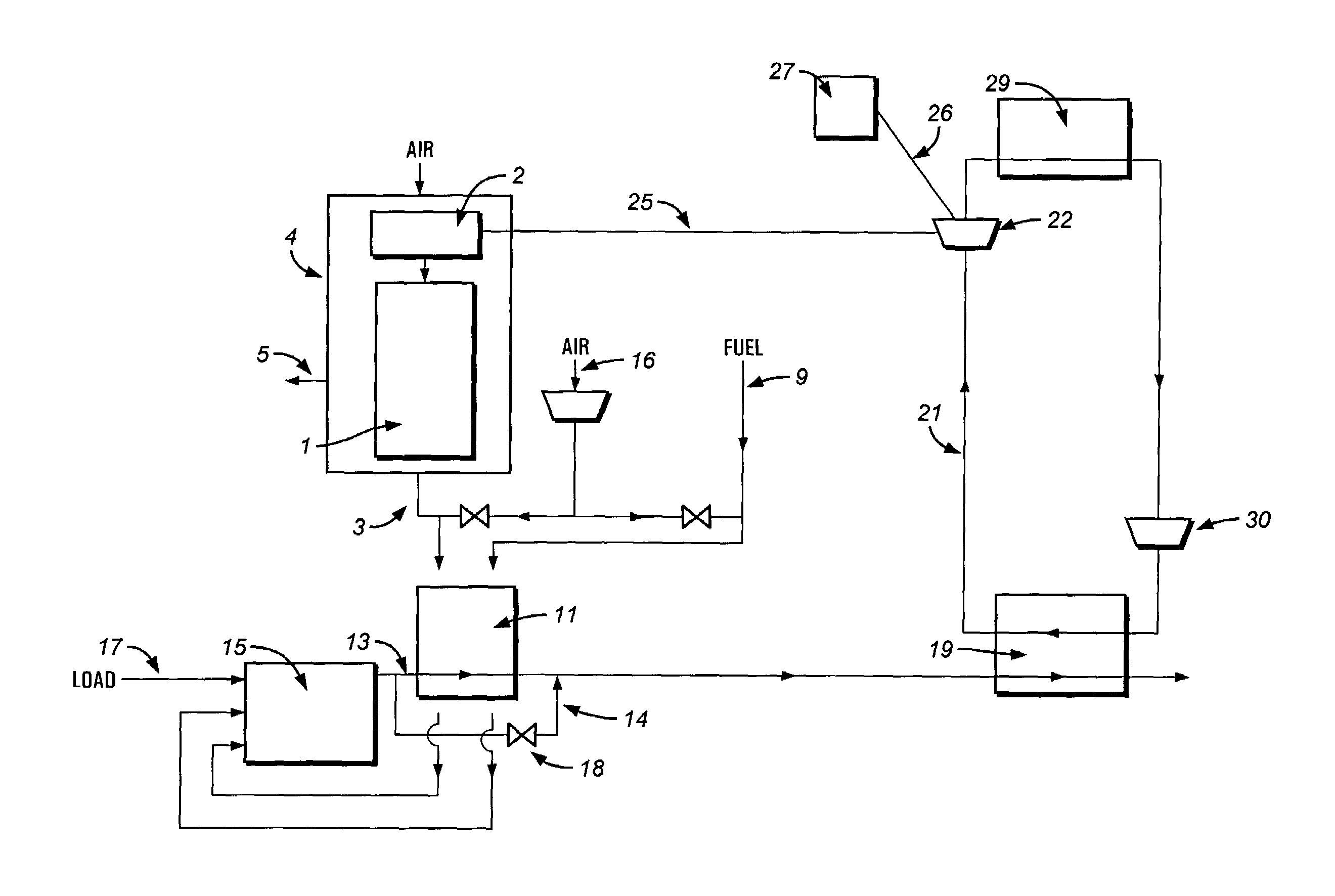
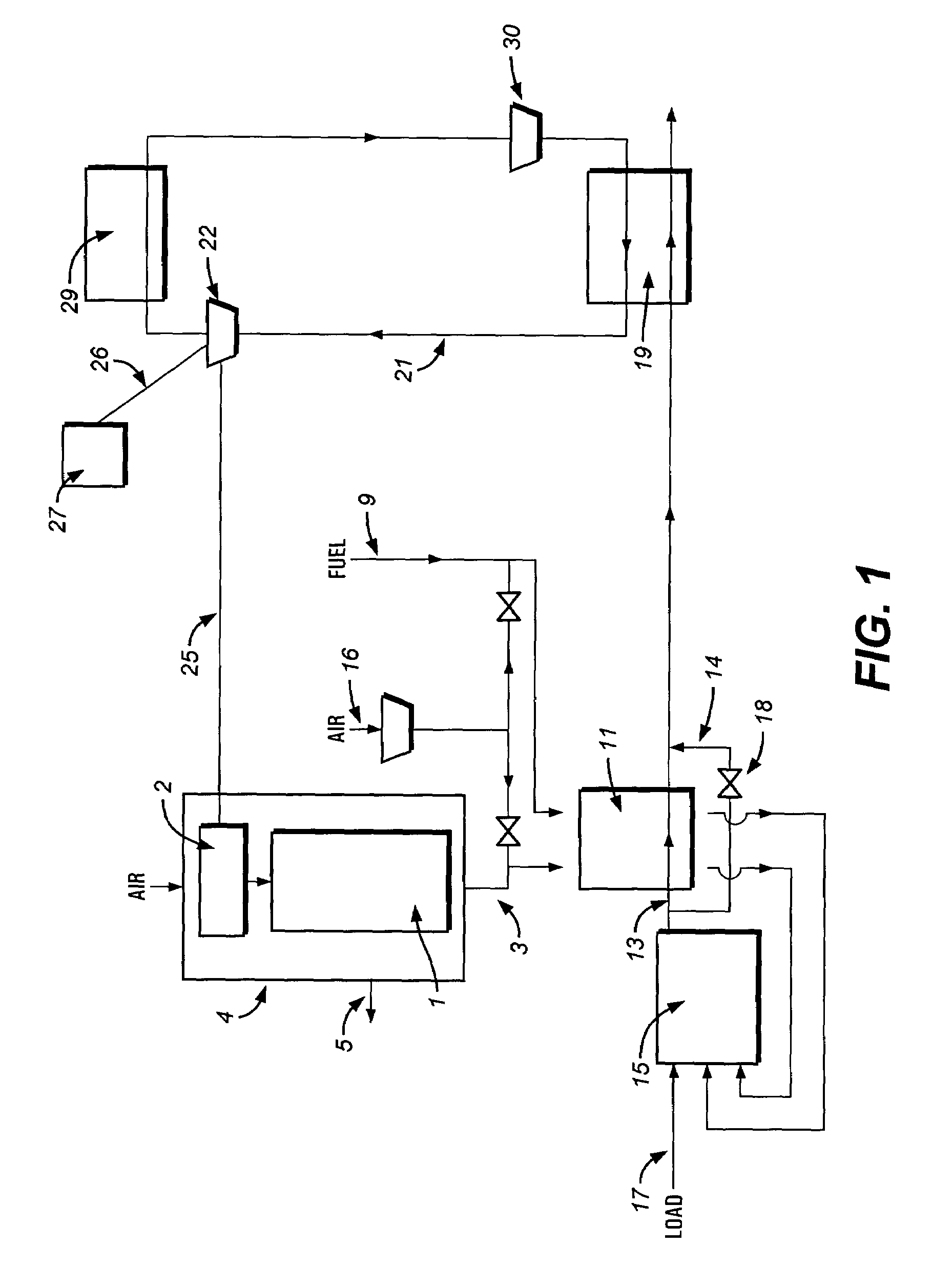
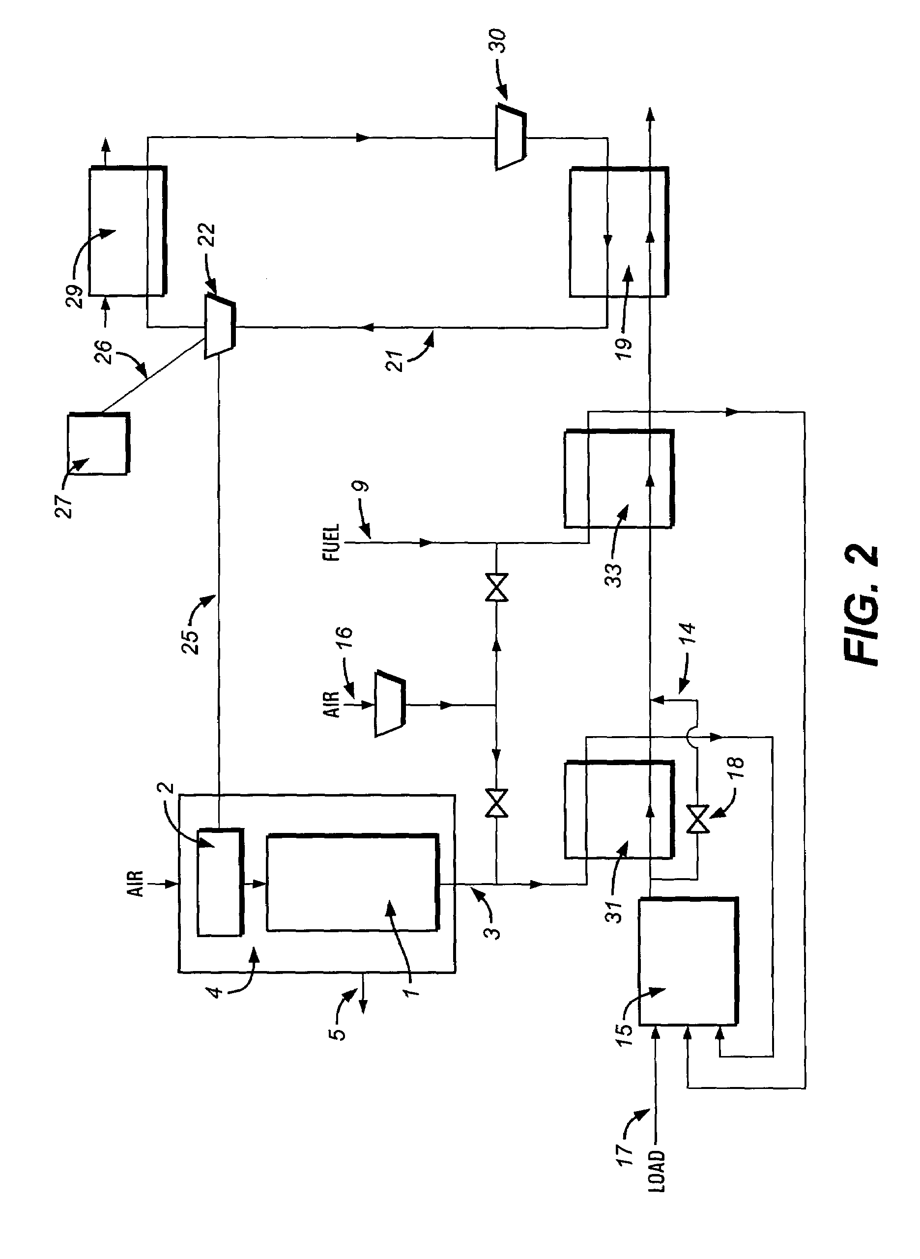
[0024]A system of the invention is for increasing the efficiency of oxygen-enriched combustion in industrial furnaces through integrated heat recovery strategies in which oxidant and fuel gases are combusted thereby producing flue gas. The system includes a source of oxygen-enriched gas, at least one heat exchanger system, a waste heat boiler and a turbine. The oxygen-enriched gas has an oxygen level higher than that of air. The heat exchanger(s) absorbs thermal energy from the flue gas and transfers it to at least one of the oxidant and fuel gases. The waste heat boiler also absorbs thermal energy from the flue gas and transfers it to feed water to produce superheated steam. The turbine produces mechanical power by allowing the superheated steam to be expanded therethrough.

[0025]A method of the invention is for increasing the efficiency of an oxygen-enriched combustion furnace in which oxidant and fuel gases are combusted such that flue gas is produced. The method includes the foll...


PUM

PropertyMeasurementUnit
Temperatureaaaaaaaaaa

Abstract

An air separation unit separates air into an oxygen-rich and oxygen-deficient gas. Fuel gas and the oxygen-rich gas are preheated at heat exchangers through which hot flue gas flows. Combustion of the preheated fuel and oxygen-rich gases result in the hot flue gas. The hot flue gas is cooled at the heat exchangers and flows through a waste heat boiler. Water and/or steam flowing through the waste heat boiler absorbs energy from the cooled flue gas thereby producing heated steam. The heated steam flows through a turbine to produce power. The power is transferred to the air separation unit, thus reducing a power requirement of the air separation unit needed to separate the air.

Description

CROSS-REFERENCE TO RELATED APPLICATIONS[0001]This application claims priority under 35 U.S.C 119 (e) to U.S. provisional application No. 60 / 359,512 filed on Feb. 25, 2002, which is incorporated herein by reference.BACKGROUND OF THE INVENTION[0002]A. Field of the Invention[0003]The invention is related to oxygen-fired furnaces. More particularly, the invention is related to methods and systems for increasing the efficiency of an oxygen-fired furnace.[0004]B. Description of the Related Art[0005]One important goal sought by those skilled in the combustion art is to increase the efficiency of the combustion process, such as by reducing capital costs, energy costs, fuel and oxidant costs, and operating costs. One method of doing so is through thermal energy recovery in furnaces. When implemented, it can often reduce energy and / or fuel requirements needed to operate the furnace. However, many of the various thermal energy techniques have their drawbacks. One of these drawbacks is financia...

Claims


Application Information

Patent Timeline
IPC IPC(8): F01K25/06F01K3/18F01K21/00F23J15/06F23L7/00F23L15/04F25J3/04
CPCF01K3/185F23J15/06F23L7/007F23L15/04F25J3/04018F25J3/04121F25J3/04521F25J3/04527F25J3/04533F25J3/04593F01K21/00Y02E20/344F25J2215/02F25J2215/50F25J2245/40C03B5/2353C03B5/237Y02E20/34Y02P40/50
Inventor PENFORNIS, ERWINMARIN, OVIDIULEROUX, BERTRANDTSIAVA, REMI P.
Owner LAIR LIQUIDE SA POUR LETUDE & LEXPLOITATION DES PROCEDES GEORGES CLAUDE
Why Eureka
Try Eureka