Coating forming method and coating forming material, and abrasive coating forming sheet

a coating forming sheet and coating technology, applied in the direction of solid-state diffusion coating, machine/engine, synthetic resin layered products, etc., can solve the problem that remelting rarely occurs in the actual operation, and achieve the effect of easy formation, simple equipment for coating formation, and easy repair

Inactive Publication Date: 2006-06-20
MITSUBISHI HEAVY IND LTD
View PDF22 Cites 34 Cited by
  • Summary
  • Abstract
  • Description
  • Claims
  • Application Information

AI Technical Summary

Benefits of technology

[0041]Therefore, so long as the heat treatment equipment is provided, the abrasive coating can be formed easily, and hence the equipment for coating formation becomes simple, as compared with the plating or thermal spraying method. Hence, even when there is no plating equipment near the gas turbine plant, the abrasive coating can be easily formed, if only a heating furnace used for the heat treatment is provided. Hence, the abrasive coating can be formed again on the rotor blade or the like, on the site. As a result, even if the abrasive coating is damaged, repair is easy.

Problems solved by technology

As a result, a problem such as remelting hardly occurs in the actual operation.

Method used


Image

  • Coating forming method and coating forming material, and abrasive coating forming sheet
  • Coating forming method and coating forming material, and abrasive coating forming sheet
  • Coating forming method and coating forming material, and abrasive coating forming sheet

Examples


Embodiment Construction

[0047]An exemplary embodiment of the present invention are explained in detail below with reference to the accompanying drawings, however, the present invention is by no means limited only to this embodiment. The components in the embodiment include one that can be assumed easily by those skilled in the art, or substantially the same one.

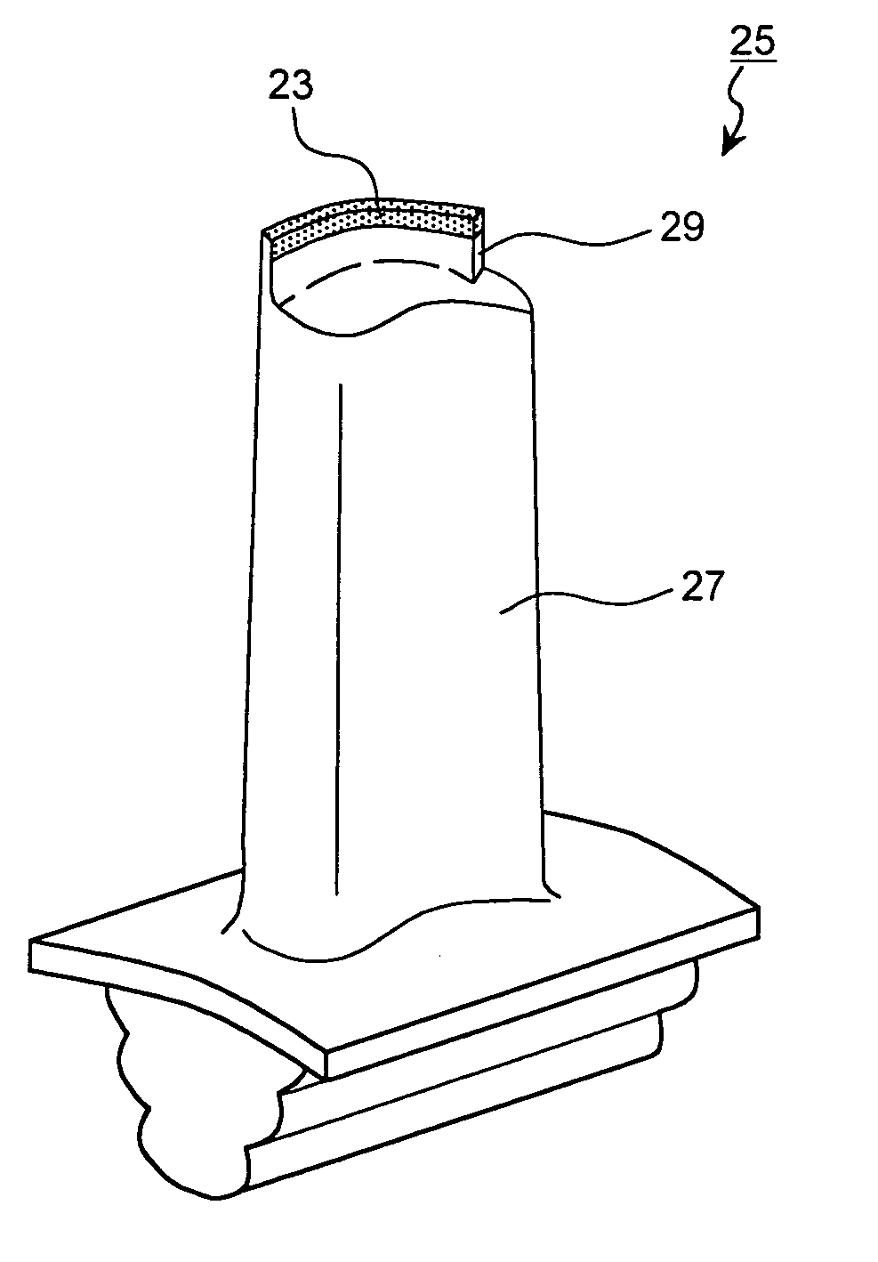
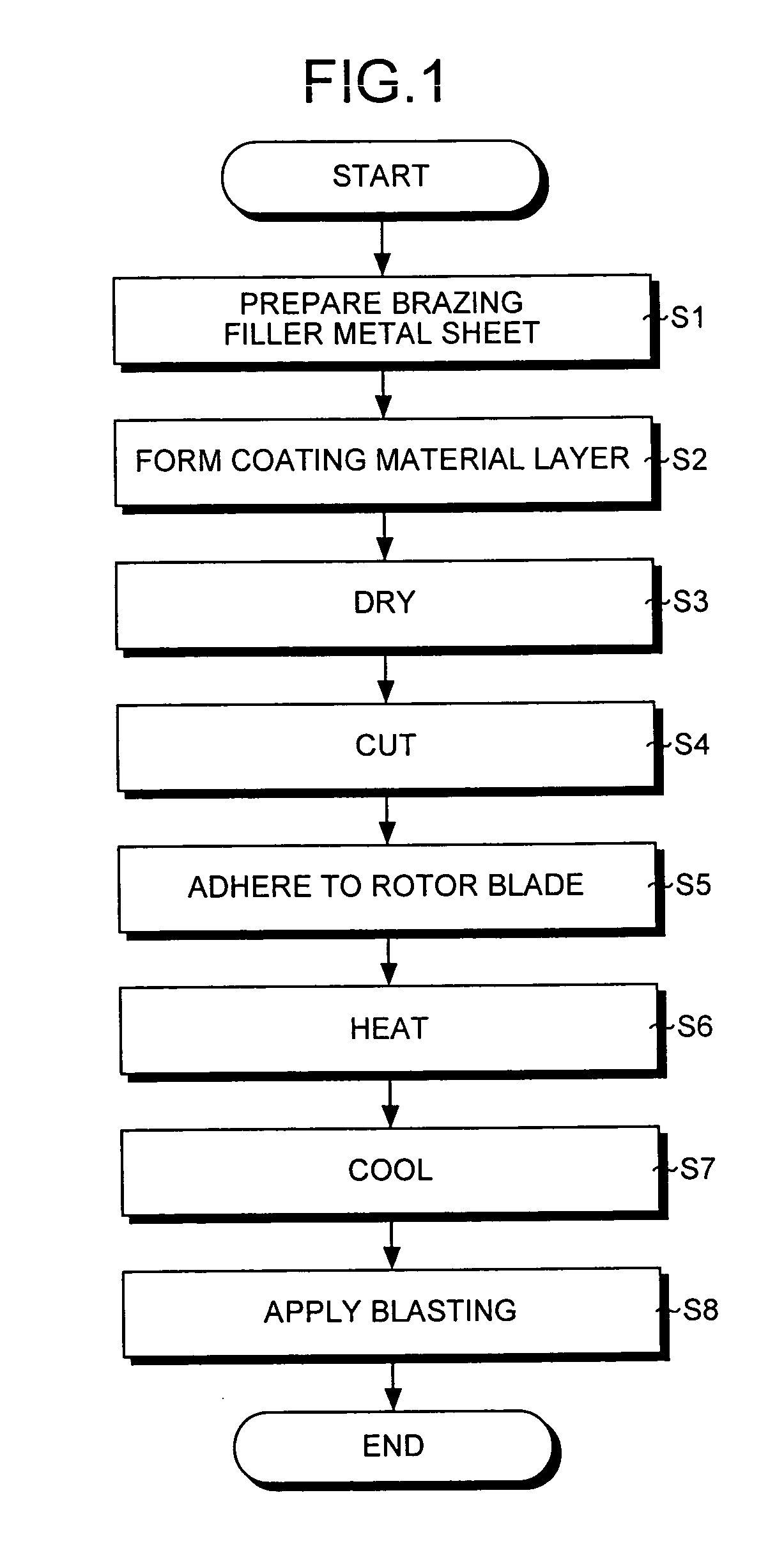
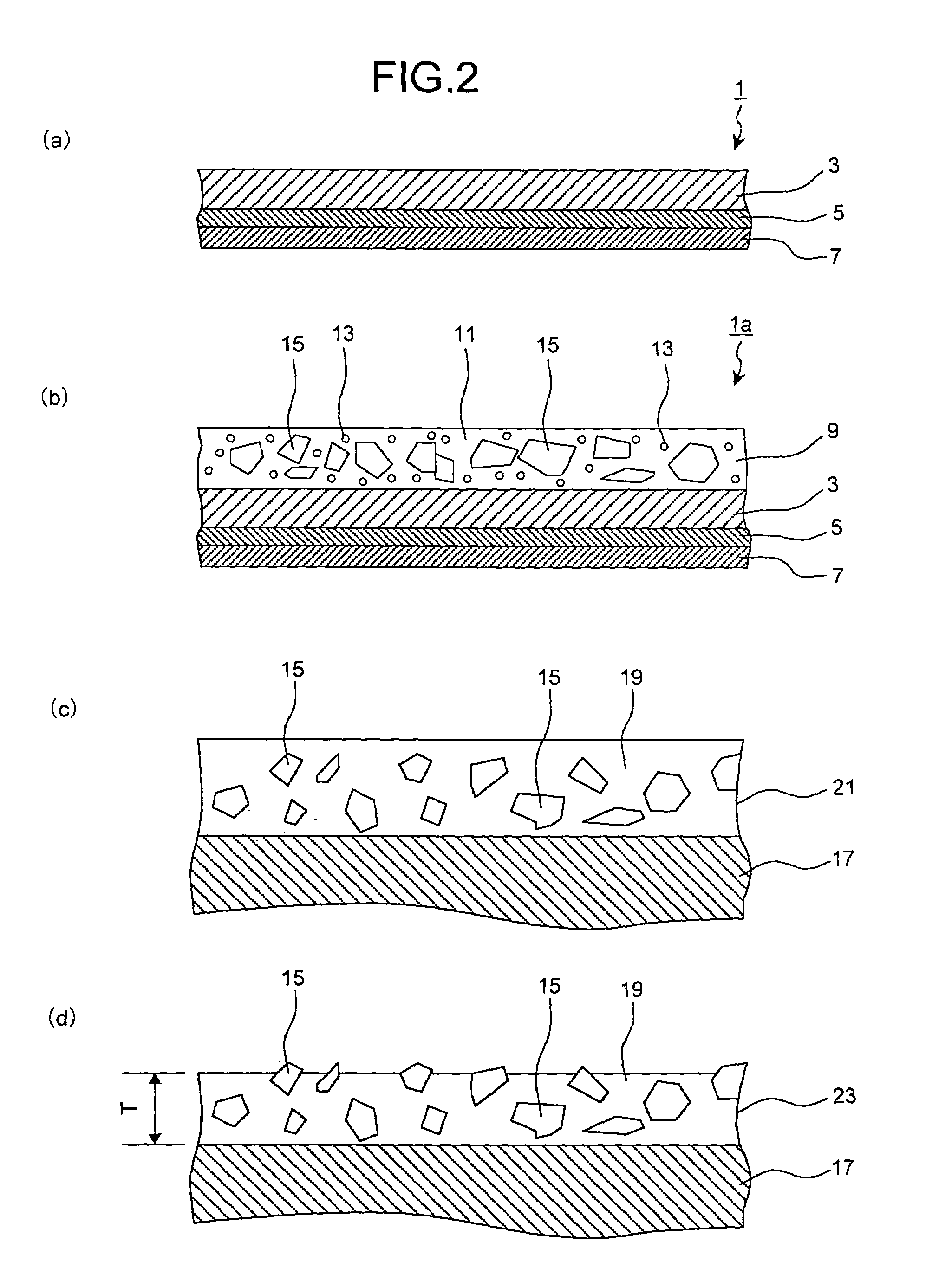
[0048]FIG. 1 is a flowchart of the coating formation method according to one embodiment of the present invention. This coating formation method is applied to a case in which a relatively simple apparatus (for example, a high vacuum heating furnace) is used, to form an abrasive coating at the tip of the rotor blade of a gas turbine. In this coating formation method, at first, a brazing filler metal sheet is prepared (step S1). FIG. 2(a) is an enlarged cross section of a part of this brazing filler metal sheet, which is comprehensively denoted by reference sign 1. This brazing filler metal sheet 1 comprises a brazing filler metal layer 3 on the upper ...


PUM

PropertyMeasurementUnit
thicknessaaaaaaaaaa
thicknessaaaaaaaaaa
particle sizeaaaaaaaaaa

Abstract

A brazing filler metal sheet is prepared. The brazing filler metal sheet includes a brazing filler metal layer, a sticking material layer, and a released paper. The brazing filler metal layer includes a brazing filler metal. A coating material layer is laminated on the brazing filler metal layer. The coating material layer includes a mixture of coating material particles and a binder. As the coating material particles, MCrAlY particles and abrasive particles are used. The coating material layer is then dried, and the brazing filler metal sheet is cut (step S4), and adhered to a rotor blade. The rotor blade is heated, to melt the brazing filler metal. The brazing filler metal diffuses due to the heat treatment holding process. A solidified layer is then formed by cooling. This solidified layer is subjected to blasting to allow the cubic boron nitride particles to protrude.

Description

TECHNICAL FIELD[0001]This invention relates to a method of forming an abrasive coating, an oxidation-resistant coating or the like on, for example, a rotor blade, a stator blade, or a shroud in a combustion engine (gas turbine, jet engine, and the like) or a steam turbine, a coating formation material, an abrasive coating formation sheet, and a rotor blade in a gas turbine on which an abrasive coating or the like is formed by this coating formation method, and a gas turbine using this rotor blade.BACKGROUND ART[0002]In a gas turbine, a predetermined clearance is provided between a tip of the rotor blade and the shroud that faces the tip of the rotor blade, so that the tip of the rotor blade and the shroud do not come in contact with each other during operation. If this clearance is too large, combustion gas leaks from the pressure surface side to the suction surface side of the rotor blade, thereby the combustion gas that can be used for driving the turbine decreases. As a result, t...

Claims


Application Information

Patent Timeline
Patent Type & Authority Patents(United States)
IPC IPC(8): B23K35/12C25D15/00B23K1/00B23K35/02C23C10/30C23C10/60C23C26/00C23C26/02F01D5/20
CPCB23K1/0018C23C10/30C23C10/60C23C26/00F01D5/20F01D11/12C23C26/02B23K35/0238B23K2201/001F05D2230/90Y02T50/67Y02T50/671Y10T428/12049Y10T29/4932B23K2101/001Y10T428/31949Y02T50/60
Inventor OHARA, MINORUMEGA, MASAHIKO
Owner MITSUBISHI HEAVY IND LTD
Why Eureka
Try Eureka