Motor driven centrifugal compressor/blower

a centrifugal compressor and motor technology, applied in the direction of positive displacement liquid engines, piston pumps, liquid fuel engines, etc., can solve the problems of low and high temperature capabilities, low and high temperature operation costs, and many oil lubricants cannot operate at very high temperatures without breaking down, so as to improve low-flow performance

Active Publication Date: 2006-06-20
R & D DYNAMICS CORPORATION
View PDF11 Cites 34 Cited by
  • Summary
  • Abstract
  • Description
  • Claims
  • Application Information

AI Technical Summary

Benefits of technology

[0023]The motor driven compressor includes a compressor housing and a rotating assembly mounted for rotation about an axis within the housing. In one aspect of the invention, the motor rotor includes a permanent magnet which is encapsulated by a sleeve press-fit over the permanent magnet with end caps connected to the sleeve. The encapsulation of the permanent magnet protects the magnet against load stresses at high rotor speeds, for example speeds in the range of 30,000 rpm or more.
[0028]In still a further aspect of the present invention, a centrifugal compressor having a compressor housing and rotating compressor assembly with an impeller includes a volute passageway leading from the discharge of the impeller for the compressed gaseous medium. In order to improve low-flow performance a plurality of airfoil-shaped diffusers are disposed in the passageway.

Problems solved by technology

This results in lower operating costs.
Low and High Temperature Capabilities—Many oil lubricants cannot operate at very high temperatures without breaking down.
At low temperature, oil lubricants can become too viscous to operate effectively.
Foil bearings, however, operate efficiently at severely high temperatures, as well as at cryogenic temperatures.
Motor material cannot handle tensile stress generated by bending.

Method used


Image

  • Motor driven centrifugal compressor/blower
  • Motor driven centrifugal compressor/blower
  • Motor driven centrifugal compressor/blower

Examples


Embodiment Construction

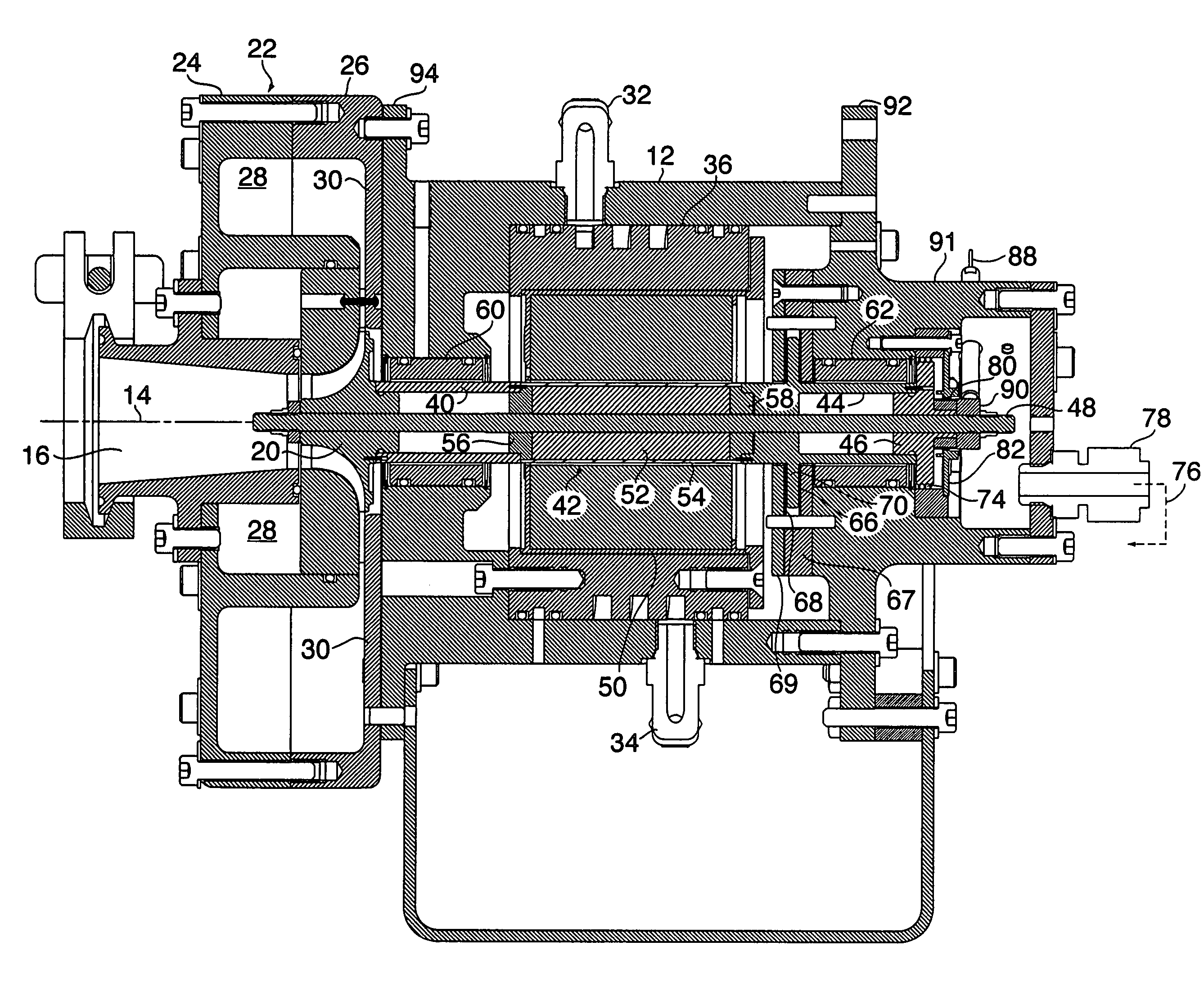
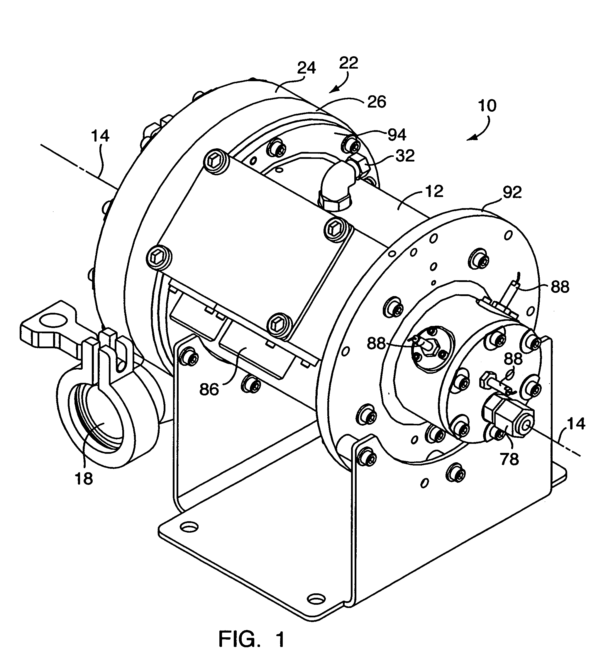
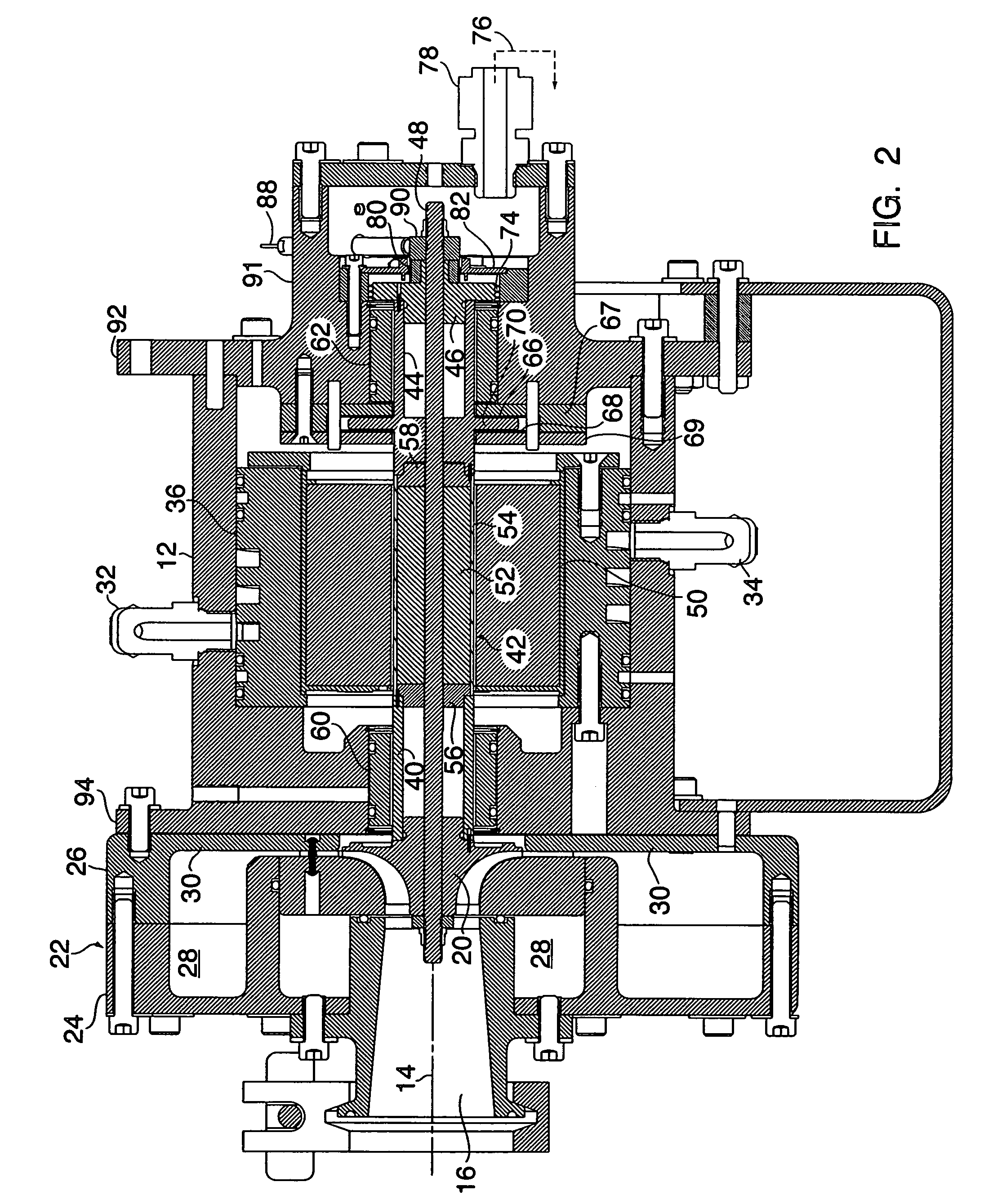
[0036]An outside view and cross section of the motor driven compressor 10 is shown in FIGS. 1 and 2 respectively. The compressor has a housing 12 which is generally symmetric about a central axis 14. At one end of the housing as shown most clearly in FIGS. 1 and 2 is an inlet 16 for the fluid medium, generally air, to be compressed, and a discharge 18 for the compressed fluid. The inlet leads to a single centrifugal compressor stage comprised of an impeller 20 and a diffuser 22 surrounding the impeller and the inlet 16. The diffuser is formed in at least two parts or pieces 24, 26 which allows the volute receiving the compressed medium from the impeller to have a square or generally rectangular cross section as shown most clearly in FIG. 2. The part 26 of the diffuser also is shown in FIG. 5 and contains airfoil shaped diffusing blades 30 which permit the compressor to operate at as low as 2% of design flow without surging.

[0037]The housing (12) also includes a cooling inlet (32) an...


PUM


Abstract

This invention provides a small, high efficiency, oil free motor driven compressor / blower suitable for providing pressurized, contamination-free gas and or air to transportation, industrial and aerospace fuel cell systems or other contaminant-intolerant applications. The motor driven compressor / blower rotor assembly is supported by foil air bearings and rotates at high speed by using a high frequency drive. The impeller is a centrifugal type design. The MDC can be easily integrated into the air management system of a fuel cell.

Description

CROSS REFERENCE TO RELATED APPLICATION[0001]This application claims the benefit of U.S. Provisional Application No. 60 / 393,259, filed Jul. 2, 2002, which is incorporated herein by reference.BACKGROUND OF THE INVENTION[0002]1. Field of Invention[0003]Various systems such as fuel cells and air separation plants to generate oxygen or nitrogen require highly efficient, compact and oil free motor driven compressors to compress working gas or air to a higher pressure level. The field of invention pertains to conception, design and manufacturing of small motor driven compressors, usually less than 10 kW, and associated technologies including their integration required for fuel cell systems for transportation, small power plants, and small air separation plants including one installed on an aircraft.[0004]Historically, compressed gas / air has been generated by various types of motor driven machines, e.g. piston, screw, vane, and centrifugal etc. To achieve high efficiency the motor must driv...

Claims


Application Information

Patent Timeline
Patent Type & Authority Patents(United States)
IPC IPC(8): F04B17/03F04D25/06F04D29/04F04D29/057F04D29/58
CPCF04D25/06F04D29/584F04D29/057F04D25/0606F04D29/053F04D29/5806
Inventor AGRAWAL, GIRIDHARI L.BUCKLEY, CHARLES W.
Owner R & D DYNAMICS CORPORATION
Why Eureka
Try Eureka