Fuel cell H2 exhaust conversion

a fuel cell and exhaust technology, applied in the field of fuel cell systems, can solve the problems of increasing the complexity of the fuel cell system incorporating the tail gas combustor, reducing the efficiency of the conversion of excess hydrogen to heat, so as to achieve no excess combustion heat or emissions, and minimal controls

Inactive Publication Date: 2006-06-20
GM GLOBAL TECH OPERATIONS LLC
View PDF3 Cites 11 Cited by
  • Summary
  • Abstract
  • Description
  • Claims
  • Application Information

AI Technical Summary

Benefits of technology

[0006]The present invention eliminates the need for the tail gas combustion process in a fuel cell system. The invention allows the excess hydrogen in the anode effluent to be converted directly to low voltage electricity with minimal controls and no excess combustion heat or emissions. The low voltage generated can be used for battery charging and / or other ancillary power needs within the fuel cell system and / or an apparatus within which the fuel cell system is operating.

Problems solved by technology

However, the conversion of the excess hydrogen to heat may not be the most efficient use of the energy contained in the anode effluent.
The heat generated by the combustor, may only be needed during certain aspects of operating the fuel cell system, such as at start up, and thereafter become a source of lost energy in the form of heat that must be dissipated from the fuel cell system.
All of the above considerations increase the complexity of a fuel cell system incorporating a tail gas combustor.

Method used


Image

  • Fuel cell H2 exhaust conversion
  • Fuel cell H2 exhaust conversion

Examples


Embodiment Construction

[0012]The following description of the preferred embodiments is merely exemplary in nature and is in no way intended to limit the invention, its application, or uses.

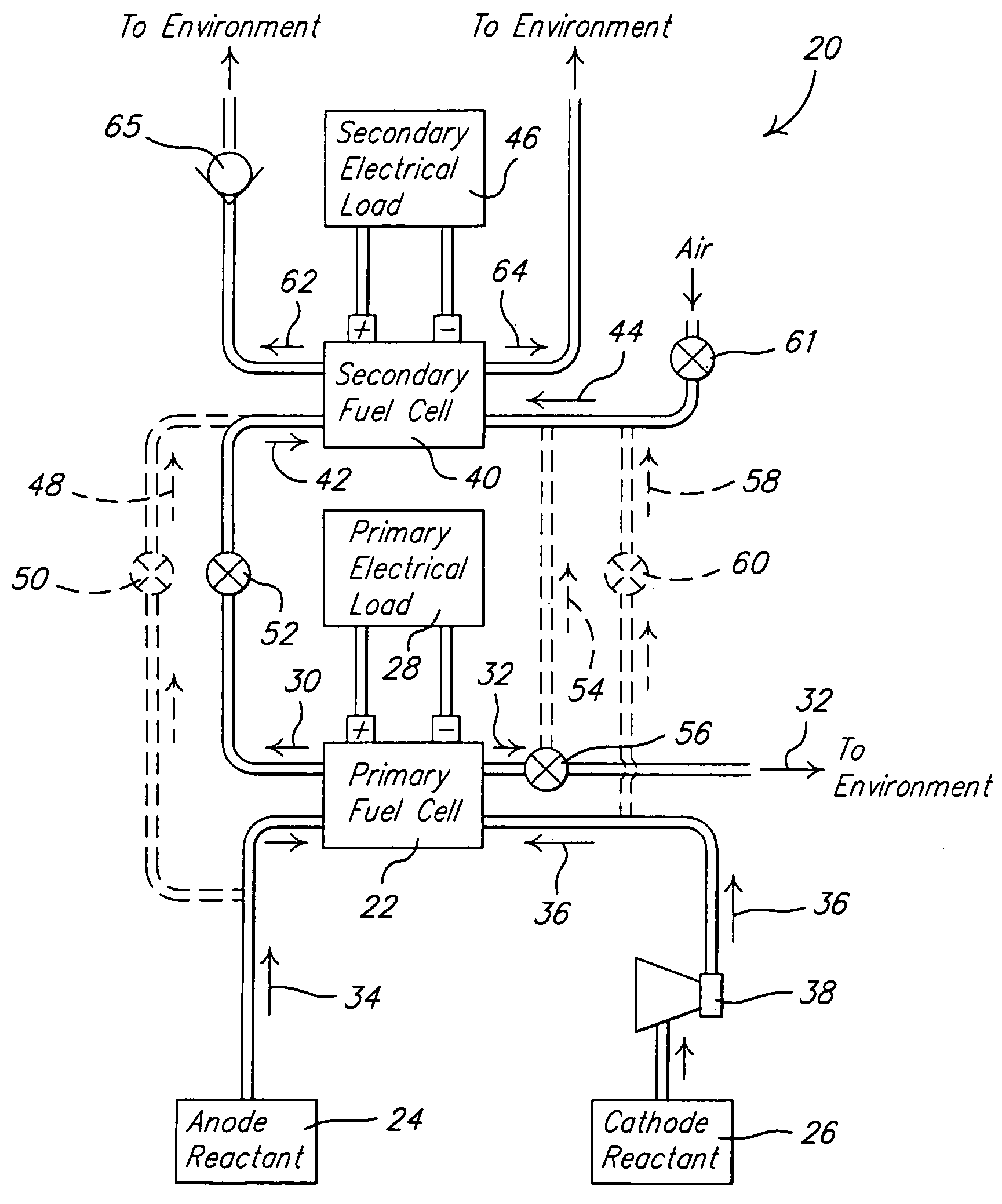
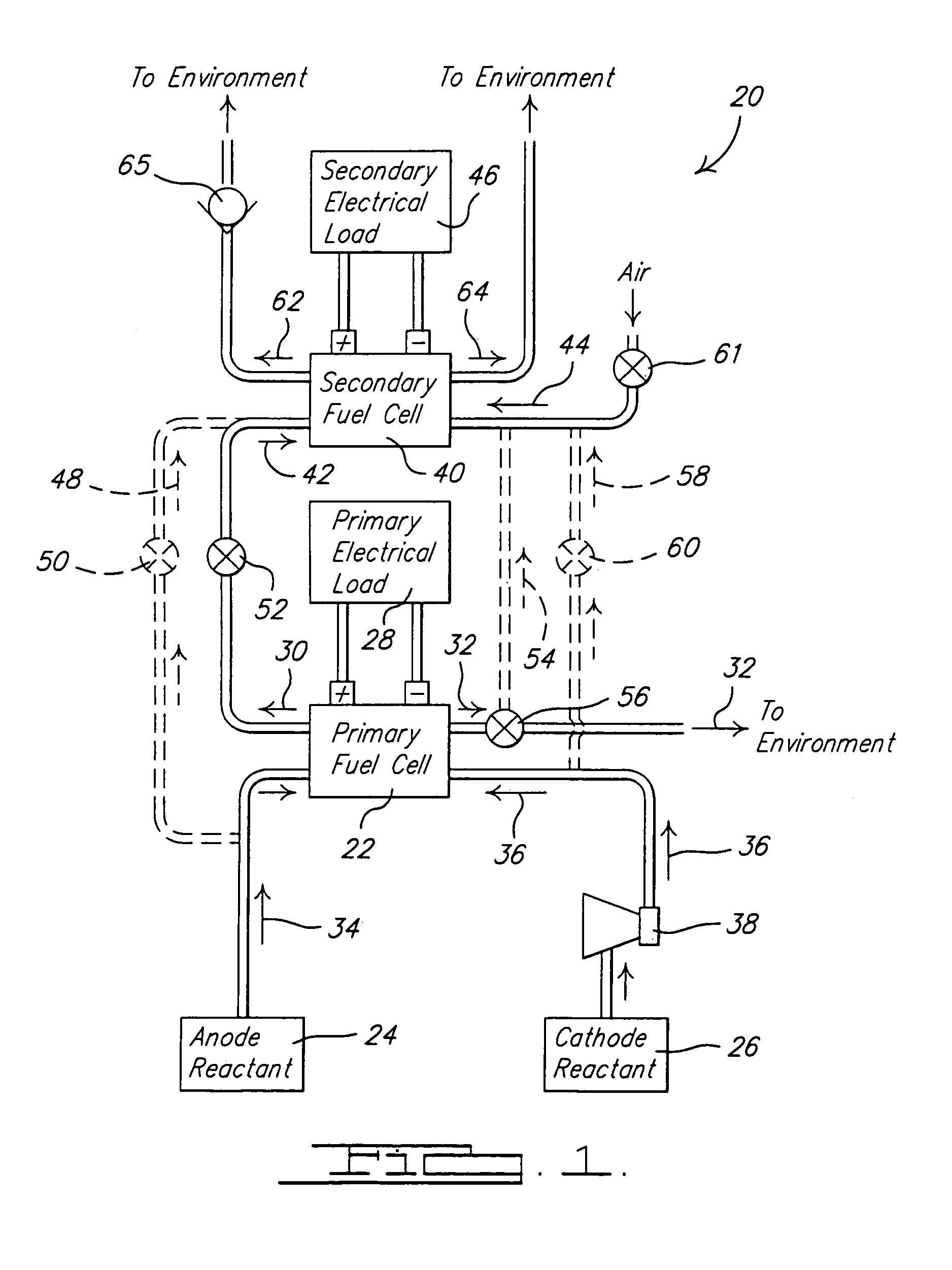
[0013]Referring to FIG. 1, a fuel cell system 20 in accordance with the principles of the present invention is shown. The fuel cell system 20 has a primary fuel cell 22 that converts an anode reactant 24 and a cathode reactant 26 into electricity to power a primary electrical load 28. The primary electrical load 28 can take a variety of forms depending upon the application within which the fuel cell system 20 is employed. For example, the primary electrical load 28 can be electric motors that are used to propel a vehicle, or other apparatuses that require an electrical current to be operated. The process of converting the anode reactant 24 and the cathode reactant 26 into electricity also produces an anode effluent 30 and a cathode effluent 32 that are exhausted from the primary fuel cell 22. The anode reactant 24 is a ...


PUM

PropertyMeasurementUnit
poweraaaaaaaaaa
hydrogen concentrationaaaaaaaaaa
concentrationaaaaaaaaaa

Abstract

A fuel cell system having first and second fuel cells that each receive anode reactant flows and cathode reactant flows. Each of the fuel cells uses the reactant flows to produce electricity. The electricity production by the fuel cells produces respective first and second anode and cathode effluents that are exhausted from the respective fuel cells. The second fuel cell is connected to and downstream from the first fuel cell so that the anode reactant flow to the second fuel cell is formed from a portion of the anode effluent exhausted from the first fuel cell.

Description

FIELD OF THE INVENTION[0001]The present invention relates to fuel cell systems and, more particularly, to fuel cell systems that have fuel cells that produce an anode effluent.BACKGROUND OF THE INVENTION[0002]H2—O2(air) fuel cells are well known in the art and have been proposed as a power source for many applications. There are several types of H2—O2 fuel cells including acid-type, alkaline-type, molten-carbonate-type, and solid-oxide-type. So called PEM (proton exchange membrane) fuel cells [a.k.a. SPE (solid polymer electrolyte) fuel cells] are of the acid-type, potentially have high power and low weight, and accordingly are desirable for mobile applications (e.g., electric vehicles). PEM fuel cells are well known in the art, and include a “membrane electrode assembly” (a.k.a. MEA) comprising a thin, proton transmissive, solid polymer membrane-electrolyte having an anode on one of its faces and a cathode on the opposite face. The MEA is sandwiched between a pair of electrically c...

Claims


Application Information

Patent Timeline
Patent Type & Authority Patents(United States)
IPC IPC(8): H01M8/18H01M8/04H01M8/10H01M2/00H01M2/14H01M8/06H01M8/24H02J
CPCB60L11/1887B60L11/1898H01M8/04089H01M8/249H01M8/0662Y02T90/34Y02E60/50Y02T10/7016B60L50/72B60L58/40Y02P70/50Y02T10/70Y02T90/40
Inventor MENON, PREMDILL, NORMAN JCHAPMAN, DARYL
Owner GM GLOBAL TECH OPERATIONS LLC
Why Eureka
Try Eureka