Method and apparatus of background suppression in MR imaging using spin locking

a technology of background suppression and spin locking, applied in the field of contrast generation of mr imaging, can solve the problems of increasing the overall scan time, increasing the likelihood of patient induced motion artifacts, and reducing patient throughput, so as to reduce the effect of effective transverse magnetization of static tissue resulting from the application of low level rf pulses and minimizing longitudinal magnetization regrowth

Active Publication Date: 2006-06-20
RGT UNIV OF CALIFORNIA +2
View PDF12 Cites 30 Cited by
  • Summary
  • Abstract
  • Description
  • Claims
  • Application Information

AI Technical Summary

Benefits of technology

[0009]The present invention is directed to a method and system of tissue or background suppression for the acquisition of image data from blood flow or tissue perfusion that overcomes the aforementioned drawbacks. Background suppression with minimal effects upon inflowing spins is achieved through a series of spin locking, low level RF pulses that cause adiabatic demagnetization of tissue with a relaxation time T1-rho that is intermediate between T1 and T2 relaxation times. In this regard, the effective transverse magnetization of static tissue resulting from the application of the series of low level RF pulses is reduced and, with the spin locking, longitudinal magnetization regrowth is minimized. As such, inflowing spins to an imaging volume may be directly imaged with significant background tissue suppression. The present invention is particularly applicable to TOF MRA and MR perfusion imaging.

Problems solved by technology

As one skilled in the art will appreciate, the creation of control or mask images as well as the subtraction of the mask or control images from the MR perfusion images increases overall scan time, decreases patient throughput, and increases the likelihood of patient induced motion artifacts.

Method used


Image

  • Method and apparatus of background suppression in MR imaging using spin locking
  • Method and apparatus of background suppression in MR imaging using spin locking
  • Method and apparatus of background suppression in MR imaging using spin locking

Examples


Embodiment Construction

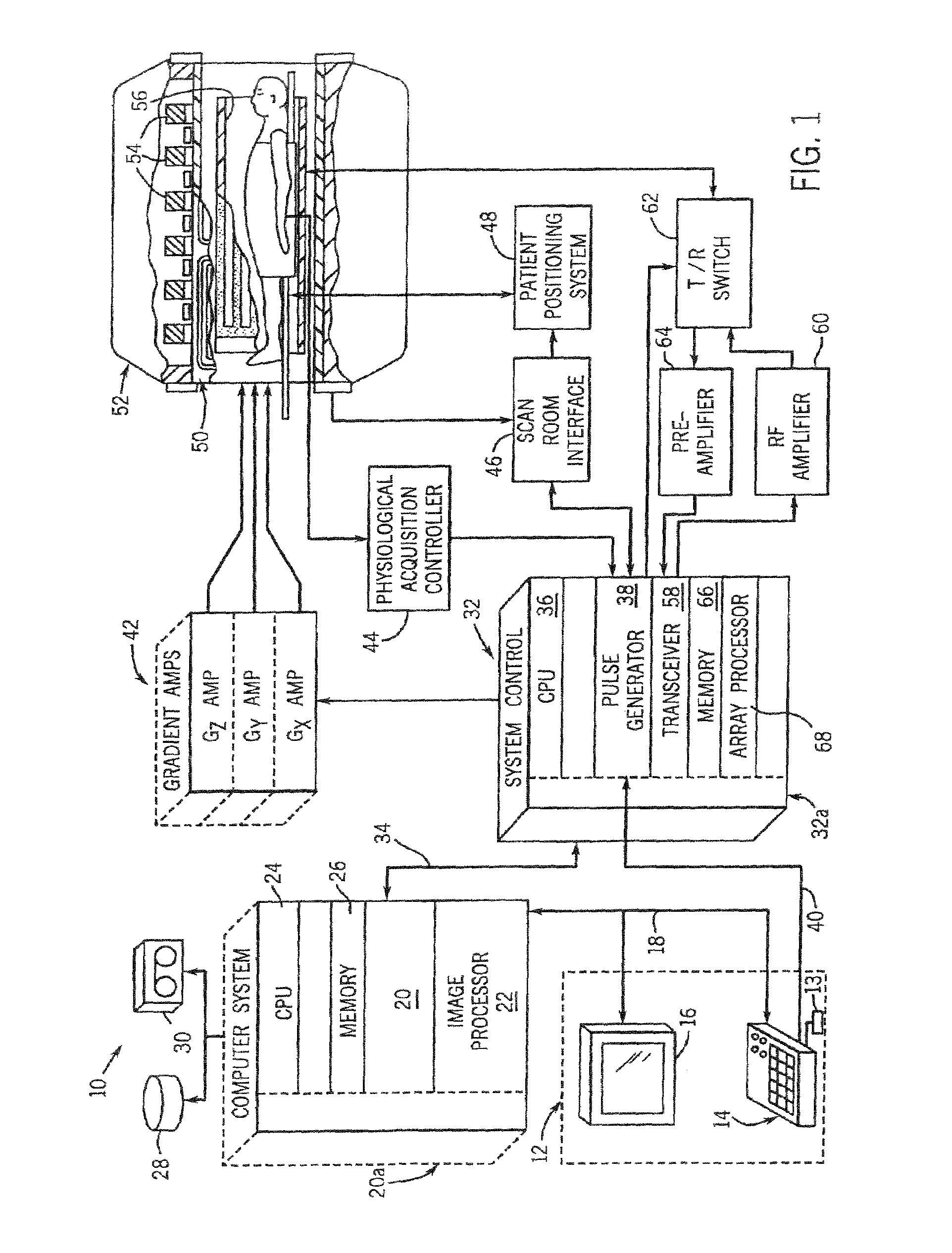
[0020]Referring to FIG. 1, the major components of a preferred magnetic resonance imaging (MRI) system 10 incorporating the present invention are shown. The operation of the system is controlled from an operator console 12 which includes a keyboard or other input device 13, a control panel 14, and a display screen 16. The console 12 communicates through a link 18 with a separate computer system 20 that enables an operator to control the production and display of images on the display screen 16. The computer system 20 includes a number of modules which communicate with each other through a backplane 20a. These include an image processor module 22, a CPU module 24 and a memory module 26, known in the art as a frame buffer for storing image data arrays. The computer system 20 is linked to disk storage 28 and tape drive 30 for storage of image data and programs, and communicates with a separate system control 32 through a high speed serial link 34. The input device 13 can include a mous...


PUM


Abstract

The present invention is directed to a method and system of tissue or background suppression for the acquisition of image data from blood flow or tissue perfusion. Background suppression with minimal effects upon inflowing spins is achieved through a series of spin locking low level RF pulses that cause adiabatic demagnetization of tissue with a relaxation time T1-rho that is intermediate between T1 and T2 relaxation times. In this regard, the effective transverse magnetization of static tissue resulting from the application of a series of low level RF pulses is reduced and, with the spin locking, longitudinal magnetization regrowth is minimized. As such, inflowing spins to an imaging volume may be directly imaged with significant background tissue suppression. The present invention is particularly applicable to time-of-flight MRA and MR perfusion imaging.

Description

BACKGROUND OF THE INVENTION[0001]The present invention relates generally to contrast generation for MR imaging and, more particularly, to a method and apparatus of background suppression particularly useful in angiography and perfusion imaging.[0002]When a substance such as human tissue is subjected to a uniform magnetic field (polarizing field B0), the individual magnetic moments of the spins in the tissue attempt to align with this polarizing field, but precess about it in random order at their characteristic Larmor frequency. If the substance, or tissue, is subjected to a magnetic field (excitation field B1) which is in the x-y plane and which is near the Larmor frequency, the net aligned moment, or “longitudinal magnetization”, MZ, may be rotated, or “tipped”, into the x-y plane to produce a net transverse magnetic moment Mt. A signal is emitted by the excited spins after the excitation signal B1 is terminated and this signal may be received and processed to form an image.[0003]...

Claims


Application Information

Patent Timeline
Patent Type & Authority Patents(United States)
IPC IPC(8): G01V3/00
CPCG01R33/563
Inventor ZAHARCHUK, GREGORY G.BRITTAIN, JEAN H.
Owner RGT UNIV OF CALIFORNIA
Why Eureka
Try Eureka