Method of manufacturing a fixed abrasive material

a technology of fixed abrasives and manufacturing methods, which is applied in the direction of gear teeth, grinding devices, manufacturing apparatus of gear teeth, etc., can solve the problems of increasing complexity of circuits, affecting the removal rate of materials, and compromising the formation of additional process layers and/or the ability to precisely position, so as to improve the uniformity of the planarized surface produced, improve the effect of one or more, and reduce the cos

Inactive Publication Date: 2006-06-27
DOW GLOBAL TECH LLC +1
View PDF48 Cites 48 Cited by
  • Summary
  • Abstract
  • Description
  • Claims
  • Application Information

AI Technical Summary

Benefits of technology

[0038]It has been found that the methods of this invention afford benefits over methods among those known in the art, including improvements in one or mor

Problems solved by technology

This is a very precise process, particularly as the size of the device structures continues to decrease and the complexity of the circuits continues to increase.
Height differences, pitch and reflectivity variations and other imperfections present in the surface of underlying layers may compromise the formation of additional process layers and/or the ability to precisely position and dimension photoresist patterns formed during subsequent lithography processes.
For example, if the abrasive particulate concentration is too low or the abrasive particle size too small, the material removal rate will generally slow and process throughput will be reduced.
Conversely, if the abrasive particulate concentration is too high, the abrasive particles are too large or the abrasive particles begin to agglomerate, the wafer surface is more likely to be damaged, the CMP process may tend to become more variable and/or the material removal rate may decrease, resulting in reduced throughput, reduced yields or device reliability and/or increased scrap.
CMP processes may experience significant performance variat

Method used


Image

  • Method of manufacturing a fixed abrasive material
  • Method of manufacturing a fixed abrasive material
  • Method of manufacturing a fixed abrasive material

Examples


example a1

[0092]An exemplary polyurethane, composition A1, was prepared by combining:[0093]80 parts WITCOBOND A-100 (WITCO Corp.);[0094]20 parts WITCOBOND W-240 (WITCO Corp.);[0095]15 parts surfactant (consisting of 9 parts STANFAX 320, 3 parts STANFAX 590, and 3 parts STANFAX 318) (Para-Chem Southern Inc.);[0096]8.5 parts ACUSOL 810A (as a viscosity modifier / thickener) (Rohm & Haas); and[0097]100 parts 500 nm ceria particles

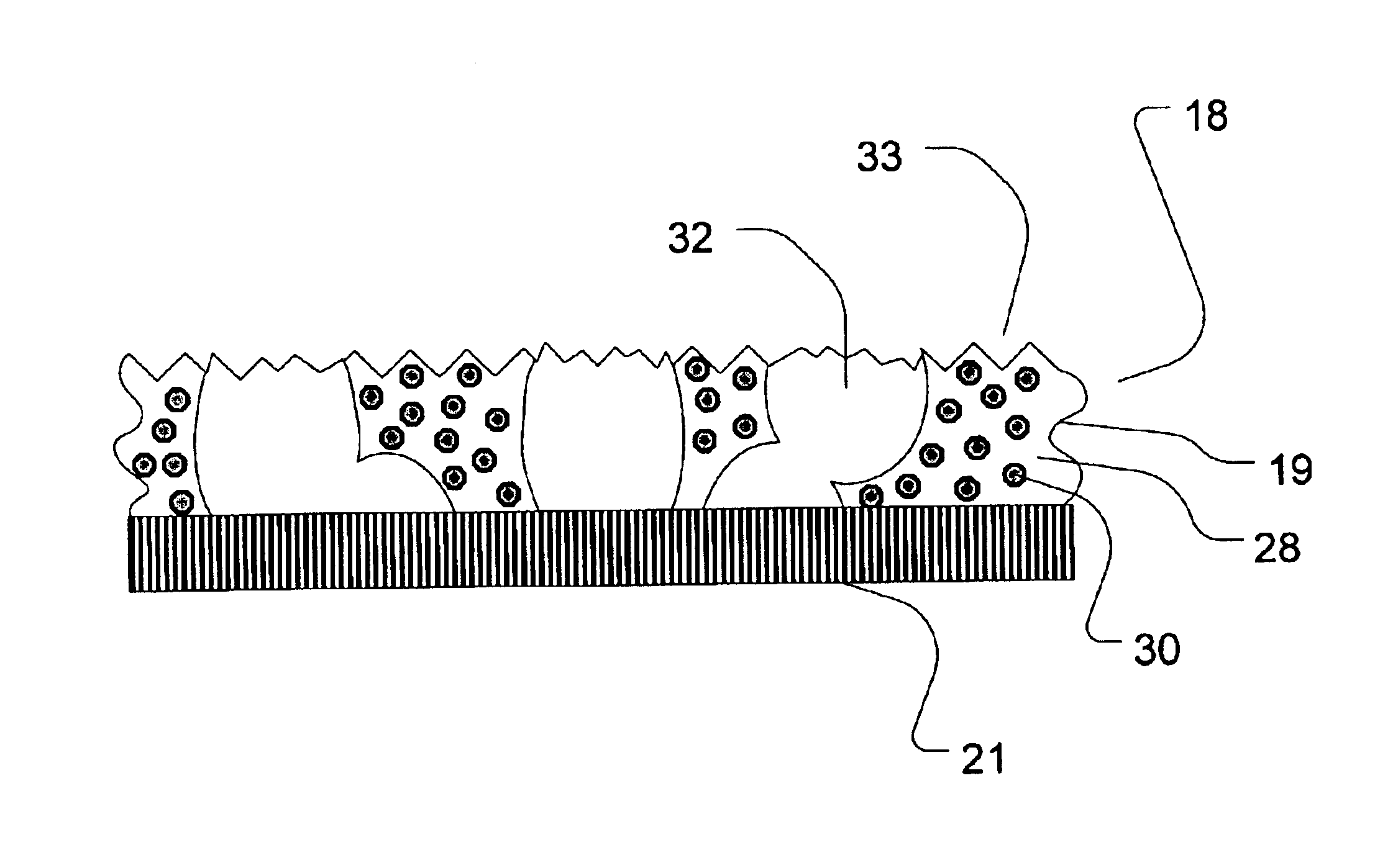
to form an aqueous dispersion (all parts reflecting dry weight). The polyurethane dispersion was then allowed to stand for approximately one hour to stabilize the viscosity at about 9500 cps. The polyurethane dispersion was then frothed using an OAKES frother to produce a froth having a density of approximately 1040 grams per liter and applied to a polycarbonate substrate to a thickness of about 1.5 mm. The froth was then cured for 30 minutes at 70° C., 30 minutes at 125° C., and 30 minutes at 150° C. to form a foam product comprising a fixed abrasive material having a fo...

example a2

[0099]Another exemplary polyurethane composition, composition A2, was prepared by combining:[0100]60 parts WITCOBOND A-100;[0101]40 parts WITCOBOND W-240;[0102]15 parts surfactant (consisting of 9 parts STANFAX 320, 3 parts STANFAX 590, and 3 parts STANFAX 318);[0103]8.5 parts ACUSOL 810A (as a viscosity modifier / thickener); and[0104]70 parts 500 nm ceria particles

to form an aqueous dispersion. The polyurethane dispersion was then allowed to stand for approximately one hour to stabilize the viscosity at about 10,000 cps. The polyurethane dispersion was then frothed using an OAKES frother to produce a froth having a density of approximately 970 grams per liter and applied to a polycarbonate substrate to a thickness of about 1.5 mm. The froth was then cured for 30 minutes at 70° C., 30 minutes at 125° C., and 30 minutes at 150° C. to form a foam product comprising a fixed abrasive material having a foam density between about 0.75 and 0.95 grams / cm3.

example a3

[0105]Another exemplary polyurethane composition, composition A3, was prepared by combining:[0106]20 parts WITCOBOND A-100;[0107]80 parts WITCOBOND W-240;[0108]15 parts surfactant (consisting of 9 parts STANFAX 320, 3 parts STANFAX 590, and 3 parts STANFAX 318);[0109]8.5 parts ACUSOL 810A (as a viscosity modifier / thickener); and[0110]70 parts 500 nm ceria particles

to form an aqueous dispersion. The polyurethane dispersion was then allowed to stand for approximately one hour to stabilize the viscosity at about 10,000 cps. The polyurethane dispersion was then frothed using an OAKES frother to produce a froth having a density of approximately 970 grams per liter and applied to a polycarbonate substrate to a thickness of about 1.5 mm. The froth was then cured for 30 minutes at 70° C., 30 minutes at 125° C., and 30 minutes at 150° C. to form a foam product comprising a fixed abrasive material having a foam density between about 0.75 and 0.95 grams / cm3.


PUM

PropertyMeasurementUnit
Fractionaaaaaaaaaa
Fractionaaaaaaaaaa
Fractionaaaaaaaaaa

Abstract

Provided is a method for manufacturing a fixed abrasive material suitable for use in CMP planarization pads from an aqueous polymer dispersion that also includes abrasive particles that involves frothing the polymer dispersion, applying the froth to a substrate, mold or carrier and curing the froth to form a fixed abrasive material having an open cell structure containing between about 5 and 85 wt % abrasive particles and a dry density of about 350 kg/m3 to 1200 kg/m3.

Description

TECHNICAL FIELD[0001]The present invention relates generally to fixed abrasive materials and, in particular, the manufacture of fixed abrasive materials suitable for use in planarizing pads for removing process material layers from the surface of semiconductor substrates.BACKGROUND[0002]Ultra large scale integrated (ULSI) semiconductor devices, such as dynamic random access memories (DRAMs) and synchronous dynamic random access memories (SDRAMs), consist of multiple layers of conducting, semiconducting, and insulating materials, interconnected within and between layers in specific patterns designed to produce desired electronic functionalities. The materials are selectively patterned on each layer of the device, using lithographic techniques, involving masking and etching the materials. This is a very precise process, particularly as the size of the device structures continues to decrease and the complexity of the circuits continues to increase. Height differences, pitch and reflect...

Claims


Application Information

Patent Timeline
IPC IPC(8): B24D11/00B24D3/32B24D13/14B24D18/00C09K23/00C09K23/10C09K23/26
CPCB24D3/32B24D18/00B24D13/147
Inventor BALIJEPALLI, SUDHAKARALDRICH, DALE J.GRIER, LAURA A.ERDEM, BEDRIMEYERS, GREGORY F.
Owner DOW GLOBAL TECH LLC
Why Eureka
Try Eureka