Method, device and security system, all for authenticating a marking

Inactive Publication Date: 2006-06-27
SICPA HLDG SA
View PDF12 Cites 58 Cited by
  • Summary
  • Abstract
  • Description
  • Claims
  • Application Information

AI Technical Summary

Benefits of technology

[0026]The method of the invention has the advantage of being applicable to any type of luminescence decay characteristics, be it exponential or not. It is in particular applicable to the authentication of mixtures of luminescents having a same particular luminescent center in environments with different decay characteristics. E.g. a mixture of YVO4:Eu and Y2O2S:Eu can be distinguished in this way from its single components.
[0027]The method according to the invention can be laid out such that a “single shot” measurement i.e. a single excitation light pulse followed by the acquisition of the corresponding luminescence response as a function of time, lasting in the order of a millisecond, is sufficient to collect the complete luminescence decay information of a probe and to compare it with the reference data. Hence, high speed operation on

Problems solved by technology

The principal shortcoming of methods of the prior art, which rely on a determination of the material's modulation-transfer function, is their inherent slowness.
This method is, however, strongly affected by variations in luminescence intensity, and therefore not easy to implement in p

Method used


Image

  • Method, device and security system, all for authenticating a marking
  • Method, device and security system, all for authenticating a marking
  • Method, device and security system, all for authenticating a marking

Examples


Embodiment Construction

[0043]The invention is further exemplified by the embodiments of security systems and of authenticating devices as described below and as shown in the following drawings:

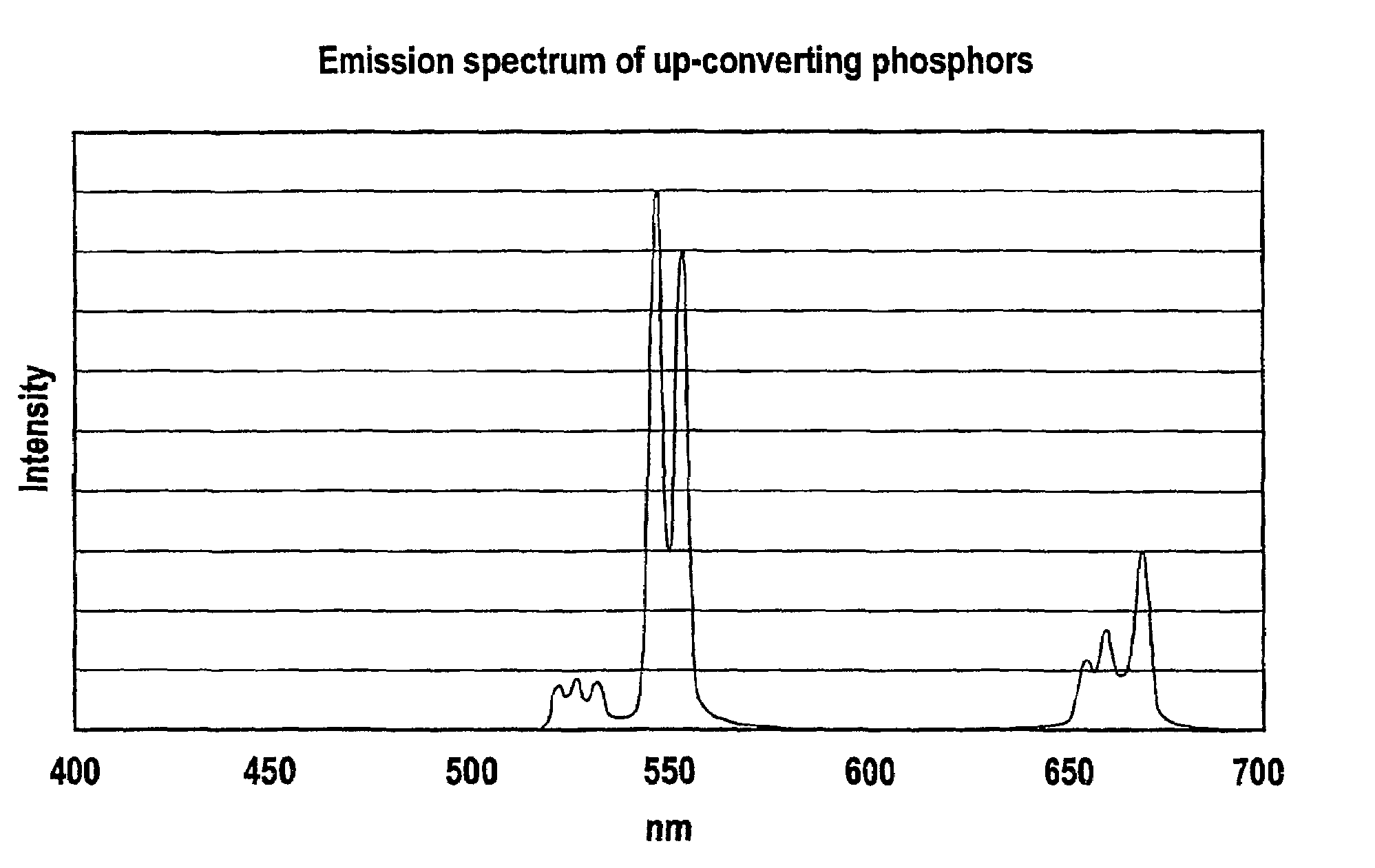
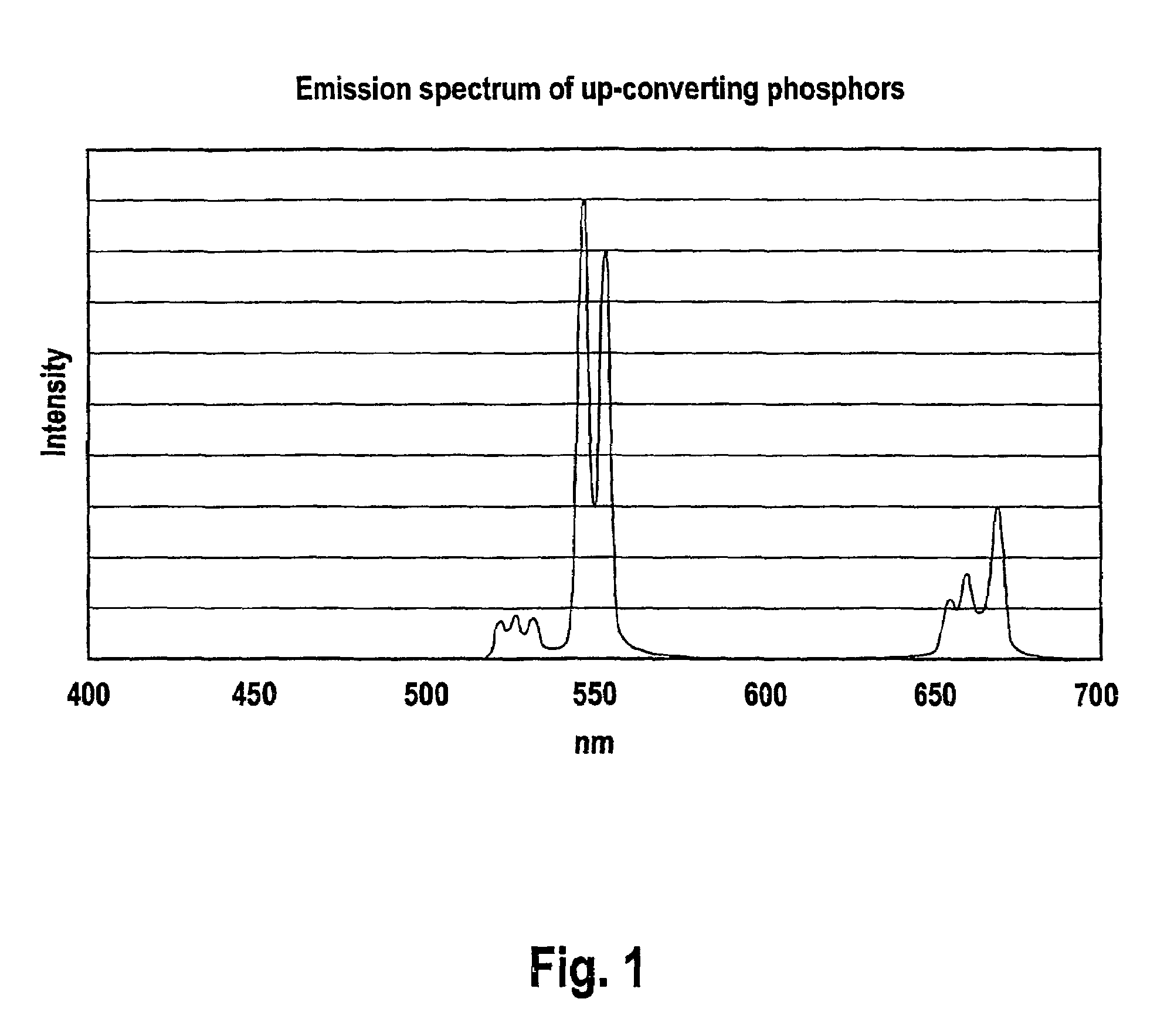
[0044]FIG. 1 shows the emission spectrum of an up-converting phosphor which can be used in connection with the invention,

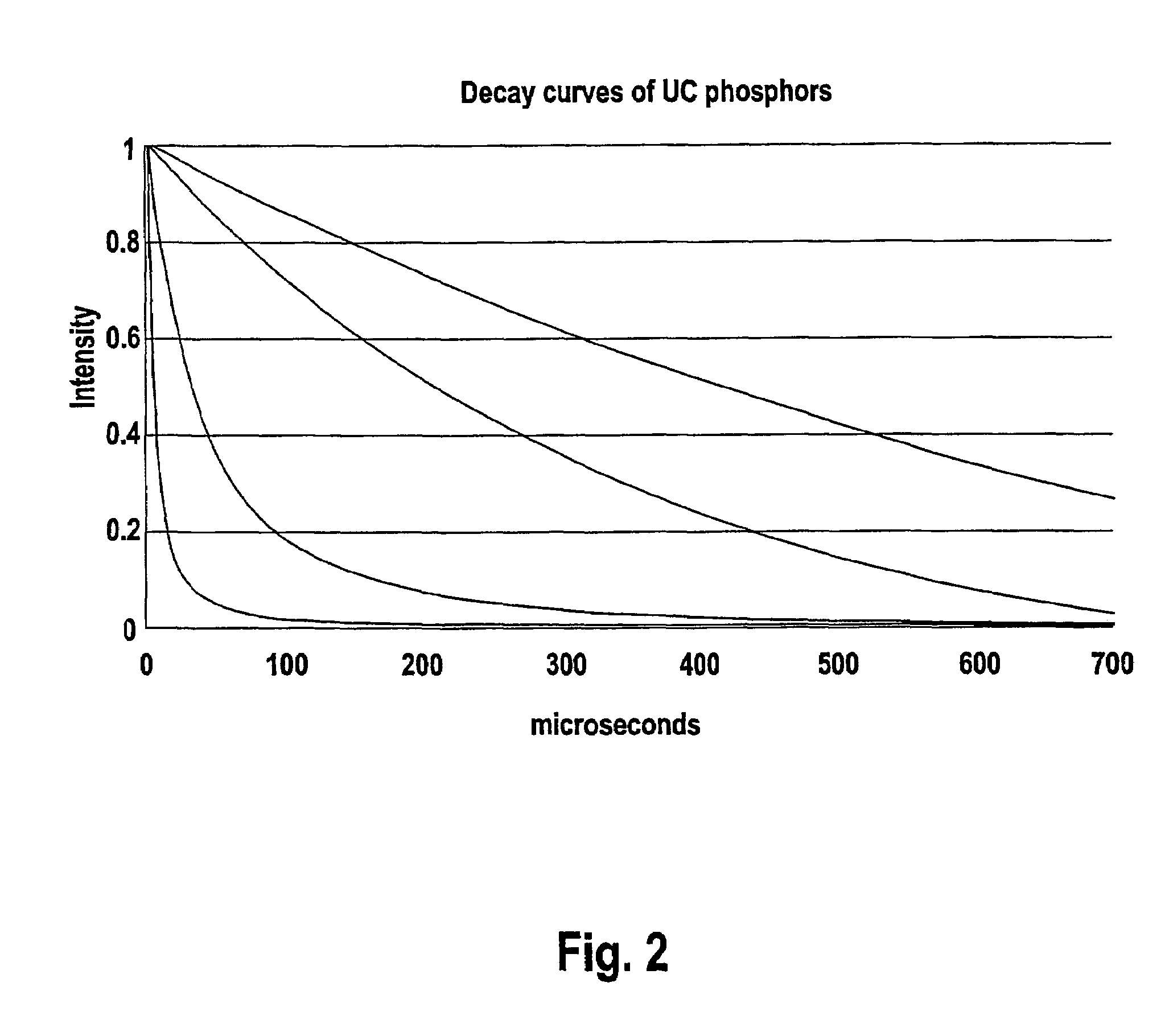
[0045]FIG. 2 shows luminescence decay curves of four different up-converting luminescent phosphors, which can be used to constitute a security system according to the invention

[0046]FIG. 3 shows the block diagram of a first embodiment of an authenticating device in accordance with the invention,

[0047]FIG. 4 shows a typical luminescence intensity / time characteristics, which can be used for authenticating purposes in accordance with the present invention,

[0048]FIG. 5 shows a schematic block diagram for a modified embodiment of a detecting device according to the invention,

[0049]FIG. 6 shows a schematic view of a more sophisticated embodiment of a detecting device according to the invention,

[0050]FIG...


PUM


Abstract

A luminescent probe marking is excited with at least one excitation pulse of at least one excitation source. The probe intensity values of emission intensity from emission radiation of the luminescent probe marking are measured in response to the excitation pulse(s) at time intervals. A probe intensity-versus-time emission function is formed of the probe intensity values, and the probe intensity-versus-time emission function is compared with at least one reference intensity-versus-time emission function after the probe intensity-versus-time emission function and the reference intensity-versus-time emission function have been normalized.

Description

FIELD OF INVENTION[0001]The invention is in the field of security markings, applied through inks or coating compositions or in bulk materials, and of documents or articles carrying such security markings. It concerns a novel method for exploiting the characteristics of certain luminescent pigments incorporated into said inks, coating compositions or articles. In particular, it deals with a method and a device allowing to exploit the characteristic luminescent afterglow of certain luminescent materials and luminescent compounds and proposes a security system for marking and authenticating an item.BACKGROUND OF THE INVENTION[0002]Luminescent materials are among the classic ingredients of security inks or coatings. They convert energy of an exciting radiation of a given wavelength into emitted light of another wavelength. The exploited luminescent emission can lie in the UV range (below 400 nm), in the visible range (400–700 nm) or in the near to mid infrared range (700–2500 nm) of the...

Claims


Application Information

Patent Timeline
IPC IPC(8): F21V9/16G06K7/10G06K7/12G06K19/14
CPCG06K19/14G07D7/121G07D7/12
Inventor MULLER, EDGAREGGER, PHILIPPSETO, MYRON
Owner SICPA HLDG SA
Why Eureka
Try Eureka