Plasma reformer for hydrogen production from water and fuel

a technology of hydrogen production and reformer, which is applied in the field of reformer, can solve the problems of increasing product gas volume, compromising hydrogen safety, and reforming techniques using catalysts that require large reaction area, so as to reduce reduce the consumption of hydrocarbon fuel, and achieve the effect of reducing the cost of hydrogen production

Inactive Publication Date: 2006-07-04
WANG CHI S
View PDF12 Cites 33 Cited by
  • Summary
  • Abstract
  • Description
  • Claims
  • Application Information

AI Technical Summary

Benefits of technology

[0009]The present invention is a reformer that dissociates a gaseous H2O/hydrocarbon fuel input mixture in a non-equilibrium thermal plasma environment. The heart of the reformer is a reaction chamber. The outer lateral wall of the reactor is an emitter electrode and the inner lateral wall is a collector electrode, the emitter electrode and the collector electrode forming an electric circuit. The emitter electrode contains a multiplicity of thin needle-like extrusions. External electricity causes electrons to be emitted copiously from the needle-like extrusions. Spindt (A Thin-Film Field Emission Cathode, J. Of Applied Physics 39, 1968. pp. 3504–3505)2 discusses how these could be produced. These high energy electrons are absorbed by hydrocarbon molecules and ionize the hydrocarbon molecules to create a greater number of lower energy electrons than were absorbed. These lower energy electrons in turn interact with H2O to dissociate it. A non-combustion pyrolysis process is used

Problems solved by technology

The introduction of air causes nitrogen dilution, increases product gas volume, causes polluting nitrogen oxides emissions, and causes formation of free oxygen, which compromises hydrogen safety.
Reforming techniques that us

Method used


Image

  • Plasma reformer for hydrogen production from water and fuel
  • Plasma reformer for hydrogen production from water and fuel
  • Plasma reformer for hydrogen production from water and fuel

Examples


Embodiment Construction

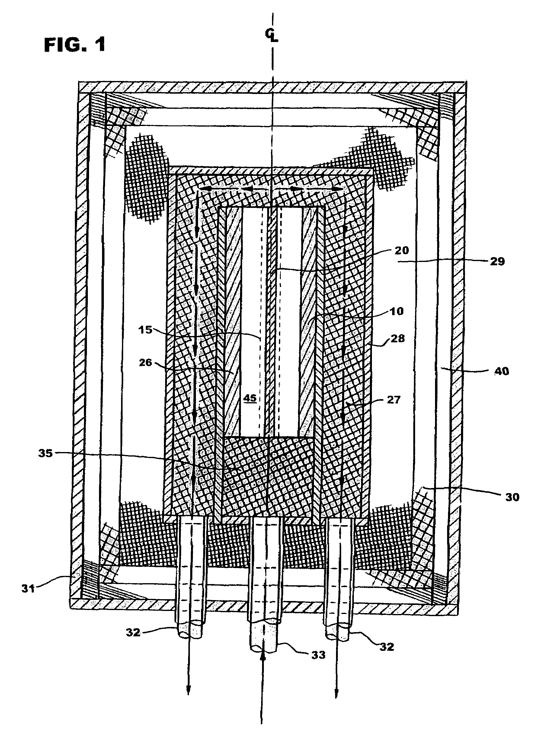
[0015]With reference to FIG. 1 the plasma reformer, has an inlet 33 to admit a flow of a gaseous mixture of H2O and hydrocarbon fuel into the plasma reformer. This mixture is preheated to a temperature in the range of 350° C. to 500° C. external to the reformer and then further heated and mixed in turbulent heating zone 35. The mixture then enters reaction chamber 45. The reaction chamber contains one or more emitter electrodes 10 and one or more collector electrodes 20. Each emitter electrode-collector electrode pair forms an electric circuit and is at high temperature being heated by an external supplemental source of electricity. The electrical energy produces active energetic electrons (harde−), and maintains and controls optimal plasma conditions. These hard electrons produce excited species ions, free radicals, and additional lower energy electrons (softe−) through electron-impaction or electron-expelling dissociation, excitation, and ionization of hydrocarbon molecules. When ...


PUM

PropertyMeasurementUnit
Temperatureaaaaaaaaaa
Diameteraaaaaaaaaa

Abstract

A plasma reformer for the chemical reforming of gaseous mixtures of water and hydrocarbon fuels for producing hydrogen. The reformer contains a reaction chamber with outer lateral walls containing emitter electrodes and inner lateral walls containing collector electrodes. The emitter electrodes and collector electrodes form an electric circuit. There are a multiplicity of thin needle-like extrusions on the emitter electrode from which a profusion of high energy electrons are emitted. These high-energy electrons dissociate the hydrocarbon fuel through absorption and ionization emitting low energy electrons in the process. These low energy electrons cause dissociation of water. Thus, dissociation of hydrocarbon fuel acts to initiate dissociation of water. The molar ratio of water to hydrocarbon fuel in the input mixture for reactions, and therefor the production of hydrogen from water, increases with carbon number of the hydrocarbon fuel.

Description

BACKGROUND OF THE INVENTION[0001]This invention pertains to a plasma reformer for dissociating H2O and hydrocarbon fuels to produce hydrogen for direct use or for use in a fuel cell and carbon oxides. More particularly it pertains to dissociating H2O into hydrogen and oxygen in a plasma reformer that uses a hydrocarbon fuel as an initiator and an intense electron field under non-equilibrium thermal plasma conditions to dissociate H2O.[0002]Hydrogen powered fuel cells have long been recognized as having great potential for stationary power generation and for transportation applications. Advantages of fuel cells include their ability to generate power more efficiently than internal combustion engines and other conventional power sources while producing essentially no pollutants. However, currently, no scalable, cost-effective, environmentally attractive hydrogen production process is available for commercialization. Hydrogen can be produced from dissociation of H2O or from reforming o...

Claims


Application Information

Patent Timeline
IPC IPC(8): B01J7/00B01J19/08
CPCB01J19/088C01B3/342C01B3/36C01B2203/1247B01J2219/0813B01J2219/0828B01J2219/083B01J2219/0869B01J2219/0883C01B2203/0216C01B2203/066C01B2203/0861C01B2203/1223C01B2203/1229B01J2219/0809
Inventor WANG, CHI S.
Owner WANG CHI S
Why Eureka
Try Eureka