Methods for reducing polarization aberration in optical systems

a technology of optical system and aberration, applied in the direction of instruments, electrical appliances, basic electric elements, etc., can solve the problems of reducing image resolution, introducing field distortion, and high cost of crytallographic orientation,

Inactive Publication Date: 2006-07-04
ASML NETHERLANDS BV
View PDF101 Cites 12 Cited by
  • Summary
  • Abstract
  • Description
  • Claims
  • Application Information

AI Technical Summary

Benefits of technology

[0016]propagating said light through one or more optical elements comprising a uniaxial birefringent medium thereby introducing second retardance aberrations substantially identical in magnitude and substantially conjugate in shape to said first retardance aberrations so as to substantially offset said first retardance aberrations.
[0023]substantially reducing said phase delay between said first and second orthogonal polarization components in said beam of light by propagating said light through second optics disposed along said optical axis, said second optics having radial and tangential eigenpolarization states that form a circularly symmetric pattern around said optical axis, said radial and tangential eigenpolarization states in said second optics being phased delayed with respect to each other opposite said phase delay between said radial and tangential eigenpolarization states of said first optics section.
[0026]substantially reducing said phase delay between said first and second orthogonal polarization components in said beam of light by propagating said light through second optics disposed along said optical axis, said second optics having radial and tangential eigenpolarization states that form a circularly symmetric pattern around said optical axis, said radial and tangential eigenpolarization states in said second optics being phased delayed with respect to each other opposite said phase delay between said radial and tangential eigenpolarization states of said first optics section.

Problems solved by technology

These crystals, however, are expensive, and certain orientations, such as the and crytallographic orientations are more expensive than others, like the crystal orientation.
When used for construction of elements of an optical system, the birefringent properties of these cubic crystalline materials may produce wavefront aberrations that significantly degrade image resolution and introduce field distortion.
These aberrations are particularly challenging for optical instruments employed in photolithography in today's semiconductor manufacturing industry where high resolution and tight overlay requirements are demanded by an emphasis on increased levels of integration and reduced feature sizes.
Strong intrinsic birefringence at this wavelength has the unfortunate effect of producing wavefront aberrations that can significantly degrade image resolution and introduce distortion of the image field, particularly for sub-micron projection lithography in semiconductor manufacturing.
Thus, there is a need to reduce these wavefront aberrations caused by intrinsic birefringence, which can degrade image resolution and cause image field distortion.

Method used


Image

  • Methods for reducing polarization aberration in optical systems
  • Methods for reducing polarization aberration in optical systems
  • Methods for reducing polarization aberration in optical systems

Examples


Embodiment Construction

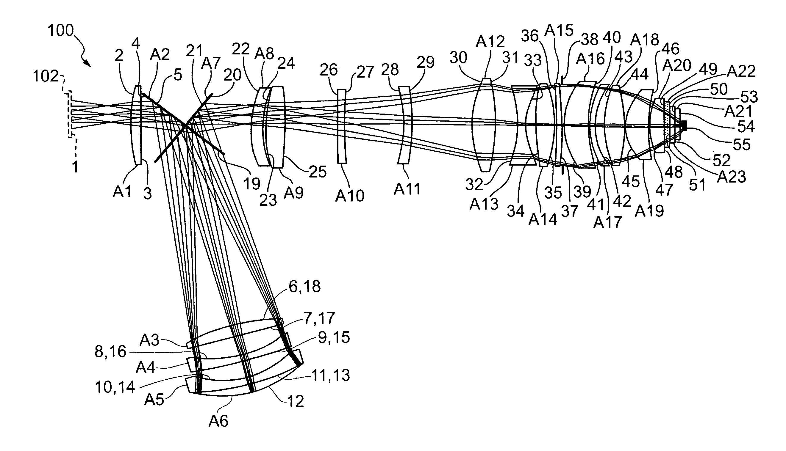
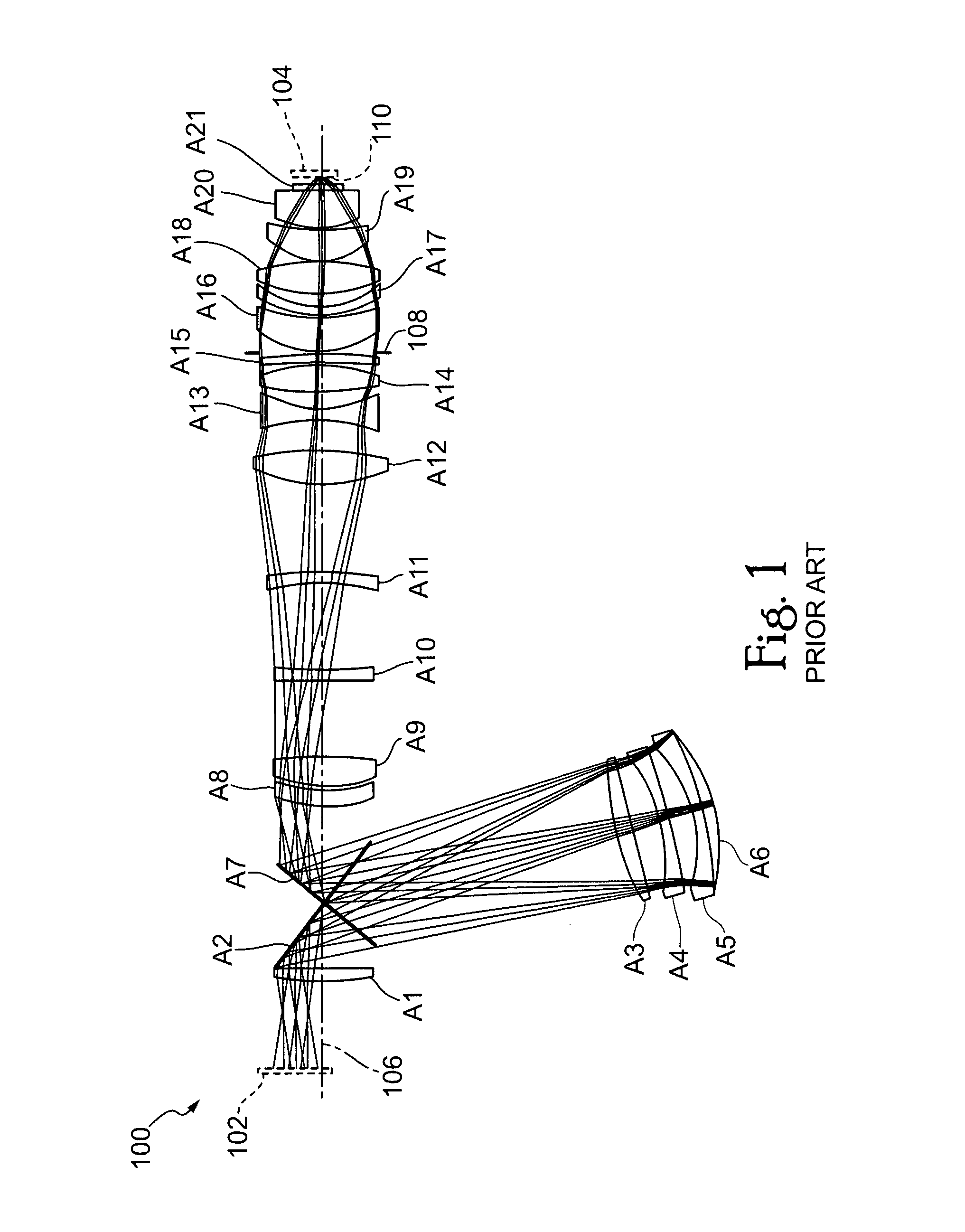
[0048]It is well-known that cubic crystalline materials like calcium fluoride are favored in lithography systems such as the high performance photolithographic tools used in the semiconductor manufacturing industry. These crystalline materials are substantially transmissive to short wavelength UV light, which provides for high optical resolution. It is also well-known, however, that these cubic crystalline materials exhibit intrinsic birefringent, i.e., an inherent anisotropy in refractive index.

[0049]Birefringence, or double-refraction, is a property of refractive materials in which the index of refraction is anisotropic, that is, the index of refraction and thus the phase velocity is different for different polarizations. For light propagating through a birefringent material, the refractive index varies as a function of polarization and orientation of the material with respect to the polarization and thus the propagation direction. Unpolarized light propagating through a birefring...


PUM

PropertyMeasurementUnit
wavelengthaaaaaaaaaa
optical wavelengthaaaaaaaaaa

Abstract

An optical system includes multiple cubic crystalline optical elements and one or more uniaxial birefringent elements in which the crystal lattices of the cubic crystalline optical elements are oriented with respect to each other to reduce the effects of intrinsic birefringence and produce a system with reduced retardance. The net retardance of the system is reduced by the cancellation of retardance contributions from the multiple cubic crystalline optical elements and the uniaxial birefringent element. The optical system may be used in a photolithography tool to pattern substrates such as semiconductor substrates and thereby produce semiconductor devices.

Description

PRIORITY APPLICATION[0001]This application claims the benefit of priority under 35 U.S.C. § 119(e) to U.S. Provisional Patent Application No. 60 / 432,688, filed Dec. 11, 2002, and entitled “Reduced Aberration in Optical Systems” as well as U.S. Provisional Patent Application No. 60 / 405,853, filed Aug. 22, 2002, and entitled “New Method of [111] Compensation Using Stress”.BACKGROUND OF THE INVENTION[0002]1. Field of the Invention[0003]The present invention relates to reducing aberration in optical systems. More particularly, the present invention relates to apparatus and methods for reducing polarization aberrations in optical systems such as lithographic imaging systems comprising cubic crystalline optical elements having intrinsic birefringence.[0004]2. Description of the Related Art[0005]In order to increase levels of device integration for integrated circuit and other semiconductor components, device features having smaller and smaller dimensions are desired. In today's rapidly ad...

Claims


Application Information

Patent Timeline
Patent Type & Authority Patents(United States)
IPC IPC(8): G02B5/30G02B17/08G02B27/28G02B5/18G02BG02B3/00G02B9/00G02B13/14G02B13/18G02B13/24G03F7/20H01L21/027
CPCG02B17/08G02B17/0892Y10S359/90
Inventor MCGUIRE, JR., JAMES P.
Owner ASML NETHERLANDS BV
Why Eureka
Try Eureka