Aligning apparatus, exposure apparatus, and device manufacturing method

a technology of exposure apparatus and alignment apparatus, which is applied in the direction of photomechanical apparatus, mechanical energy handling, instruments, etc., can solve the problems of difficult to perform highly accurate position control, use in vacuum, and easy transmission of vibration from the stator, so as to suppress the influence of coil heat generation and high accuracy the effect of alignmen

Inactive Publication Date: 2006-07-11
CANON KK
View PDF19 Cites 18 Cited by
  • Summary
  • Abstract
  • Description
  • Claims
  • Application Information

AI Technical Summary

Benefits of technology

[0008]According to the present invention, an aligning apparatus which can perform highly accurate alignment while suppressing the influence of coil heat generation can be provided.

Problems solved by technology

Regarding Japanese Patent Laid-Open No. 08-006642, if the movable element is levitated by pneumatic pressure, a problem arises for use in a vacuum.
If the driving scheme is the pulse motor scheme using Sawyer's principle, vibration from the stator tends to be transmitted easily, and highly accurate position control is difficult to perform.
Accordingly, the coil is susceptible to disturbance from the cable.
In this respect, as well, high alignment accuracy control is difficult to perform.
When high position accuracy is required in the posture and vertical direction as in an exposure apparatus, with this driving scheme, a fine movement stage for Z tilt direction control must be provided, making the structure complicated.
If the lower core portion is made of a magnetic material as in Japanese Patent Laid-Open No. 11-069764, cogging occurs undesirably, and highly accurate alignment control is difficult to perform.

Method used


Image

  • Aligning apparatus, exposure apparatus, and device manufacturing method
  • Aligning apparatus, exposure apparatus, and device manufacturing method
  • Aligning apparatus, exposure apparatus, and device manufacturing method

Examples


first embodiment

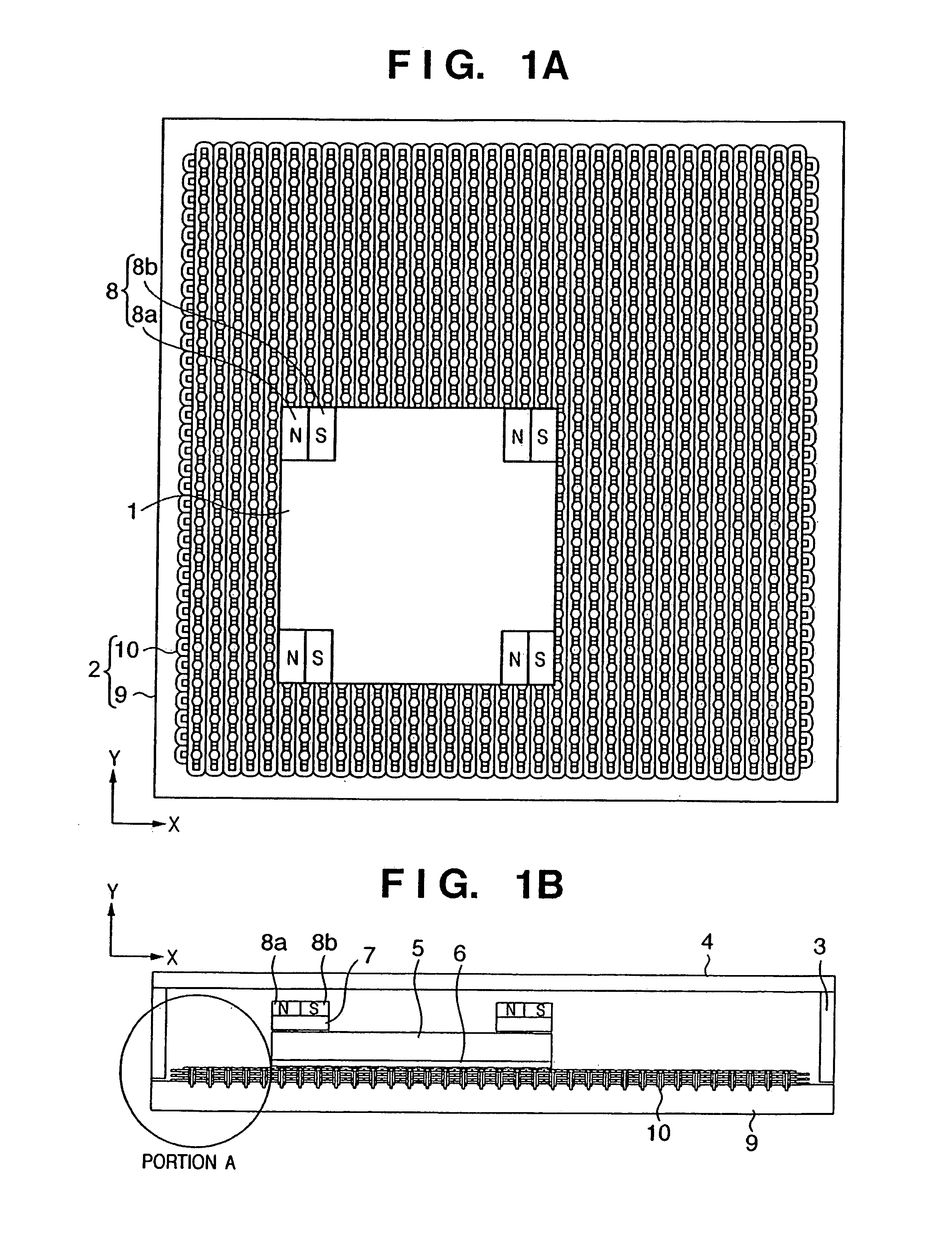
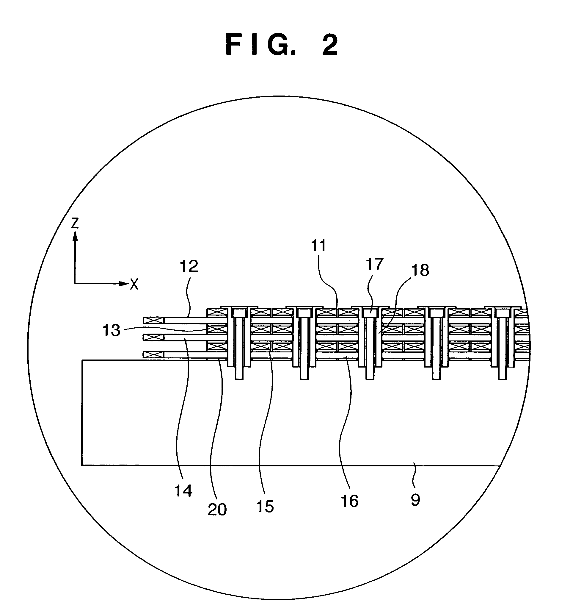
[0040]FIGS. 1A and 1B show the first embodiment, in which FIG. 1A is a view seen from the vertical (Z) direction and FIG. 1B is a view seen from the horizontal (Y) direction. An aligning apparatus has a movable element unit 1, which moves with an object mounted on it, a stator unit 2, and an attracting plate 4, which is supported by the stator unit 2, through support columns 3. The movable element unit 1 is a single plate and has a substantially rectangular parallelepiped top plate 5, a magnet unit 6, which is formed under the top plate 5 and formed of a plurality of permanent magnets, and permanent magnets 8, which are provided to the four corners on the top plate 5 through yokes 7. As the material of the top plate 5, one having a high specific rigidity such as a ceramic material is preferable. The attracting plate 4 faces the upper portions of the permanent magnets 8 in a noncontact manner and is made of a magnetic material.

[0041]According to this embodiment, two permanent magnets...

second embodiment

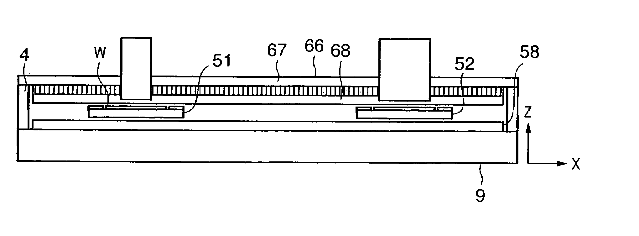
[0090]FIGS. 16A and 16B show the second embodiment. In the first embodiment, one movable unit is provided. In the second embodiment, two movable units are provided. The arrangement having two movable units in this manner attracts attention in recent years as a wafer stage used in an exposure apparatus. When exposure operation of exposing a pattern onto a wafer and measurement (alignment) operation of measuring the position of the pattern exposed the last time are performed simultaneously, an increase in throughput can be expected.

[0091]FIG. 16A is a view of movable stages 51 and 52 seen from the Z-axis direction. The two movable stages 51 and 52 can move in a measurement region 54 and exposure region 53, respectively. A projection optical unit 55, e.g., a projection lens, which exposes the pattern of the wafer mounted on the movable element is arranged above the exposure region 53. A measurement optical unit 56, e.g., an off-axis scope, which measures the position of the exposed pat...

third embodiment

[0118]FIG. 23 shows an example in which the aligning apparatus (stage device) described above is employed in a vacuum atmosphere. The aligning apparatus is applied to an exposure apparatus, which uses EUV (Extreme Ultra Violet) light, as exposure light. The EUV exposure apparatus prints a reticle pattern onto a wafer by using light having a very short wavelength of about 13 nm. When using short-wavelength light such as EUV light, a vacuum atmosphere is needed to prevent attenuation of the energy. In order to prevent contamination of the EUV optical system, a high-vacuum atmosphere is needed around the optical system.

[0119]A stage device as an aligning apparatus is set inside a partition 90 (vacuum chamber) having an interior filled with a vacuum atmosphere. The structure and operation of a movable stage 1 and stator unit 2 can be basically the same as those of the embodiments and modifications described above, and a detailed description thereof will accordingly be omitted.

[0120]A ma...


PUM

PropertyMeasurementUnit
currentaaaaaaaaaa
wavelengthaaaaaaaaaa
forceaaaaaaaaaa

Abstract

An aligning apparatus includes a moving member, a magnetic member arranged vertically above the moving member, a stator unit which is arranged vertically below the moving member and has a plurality of coreless coils, a first magnet unit which is provided to the moving member and generates a force with the magnetic member, and a second magnet unit which is provided to the moving member and generates a force with the stator unit. The aligning apparatus has no coils between the magnetic member and the moving member.

Description

FIELD OF THE INVENTION[0001]The present invention relates to an aligning apparatus for aligning an object and, more particularly, an aligning apparatus in a manufacturing apparatus such as an exposure apparatus for manufacturing devices such as semiconductor devices or liquid crystal devices, which is suitably used to align a substrate and / or an original.BACKGROUND OF THE INVENTION[0002]In recent years, in an aligning apparatus, e.g., a stage device for an exposure apparatus, which is required for high alignment accuracy, a plane motor type aligning apparatus has been attracting attention. As a plane motor type aligning apparatus, for example, an aligning apparatus described in Japanese Patent Laid-Open No. 08-006642 is available. According to Japanese Patent Laid-Open No. 08-006642, the aligning apparatus uses a movable element obtained by winding a coil around an inductor toothed iron core and a stator obtained by forming tooth-like projections on a magnetic base. The movable elem...

Claims


Application Information

Patent Timeline
Patent Type & Authority Patents(United States)
IPC IPC(8): H02K41/00H02K7/09H01L21/68G03F7/20H01L21/027H02K9/19H02K41/03
CPCG03F7/70758H02K41/031H02K3/47H02K2201/18H02K16/02
Inventor KORENAGA, NOBUSHIGE
Owner CANON KK
Why Eureka
Try Eureka