Image forming characteristics measuring method, image forming characteristics adjusting method, exposure method and apparatus, program and storage medium, and device manufacturing method

a technology of image forming characteristics and measuring methods, applied in the direction of programme control, printers, instruments, etc., can solve the problems of insufficient correction of only the seidel's five aberrations, insufficient accuracy of data obtained, and difficulty for service technicians repairing or adjusting the exposure apparatus or users to obtain such data, etc., to achieve high integration micro-devices, good yield, and good precision

Inactive Publication Date: 2006-07-11
NIKON CORP
View PDF51 Cites 27 Cited by
  • Summary
  • Abstract
  • Description
  • Claims
  • Application Information

AI Technical Summary

Benefits of technology

[0013]The present invention was made under such circumstances, and has as its first purpose to provide an image forming characteristics measuring method in which a targeted image forming characteristic of a projection optical system can be measured easily and accurately.
[0014]The second purpose of the present invention is to provide an image forming characteristics adjusting method in which an image forming characteristic of a projection optical system can be adjusted easily and accurately.
[0015]The third purpose of the present invention is to provide an exposure method in which fine patterns can be formed with good precision on a substrate.

Problems solved by technology

For example, when coma is large, the image of the pattern is not resolved, therefore, when aberration such as distortion, spherical aberration, astigmatism are measured in this state, accurate data cannot be obtained.
Thus, correcting only the Seidel's five aberrations is not sufficient enough, and requirements are pressing for an overall adjustment of the image forming characteristics of the projection optical system, including the higher order of aberrations.
However, because data of individual lens elements are confidential for the exposure apparatus maker, it is usually difficult for a service technician repairing or adjusting the exposure apparatus or a user to obtain such data.
In addition, since the light-ray-trace computation requires an enormous amount of time, it is not realistic for the service technician to perform the computation on site.

Method used


Image

  • Image forming characteristics measuring method, image forming characteristics adjusting method, exposure method and apparatus, program and storage medium, and device manufacturing method
  • Image forming characteristics measuring method, image forming characteristics adjusting method, exposure method and apparatus, program and storage medium, and device manufacturing method
  • Image forming characteristics measuring method, image forming characteristics adjusting method, exposure method and apparatus, program and storage medium, and device manufacturing method

Examples


Embodiment Construction

[0103]An embodiment of the present invention will be described below with reference to FIGS. 1 to 9B.

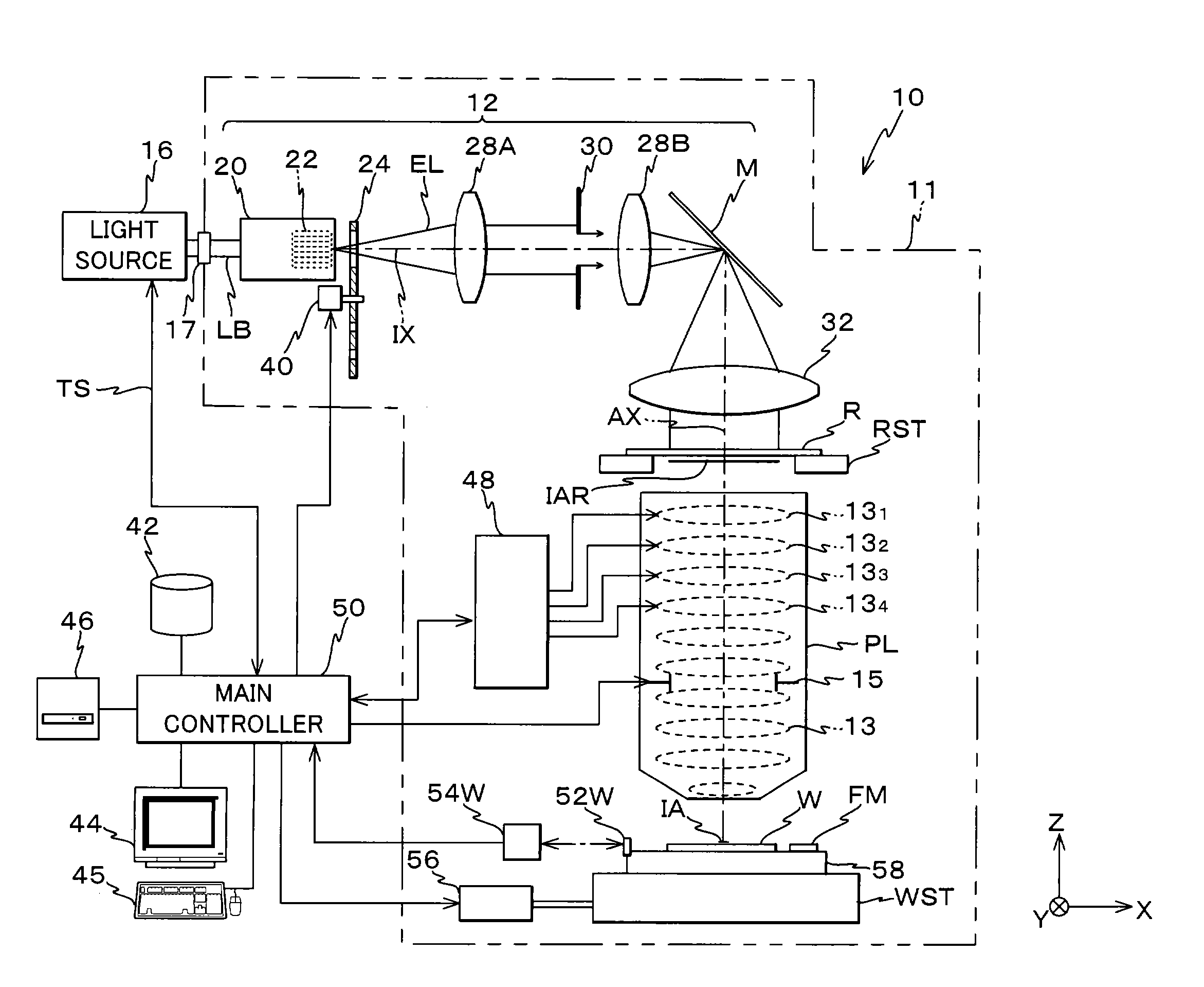
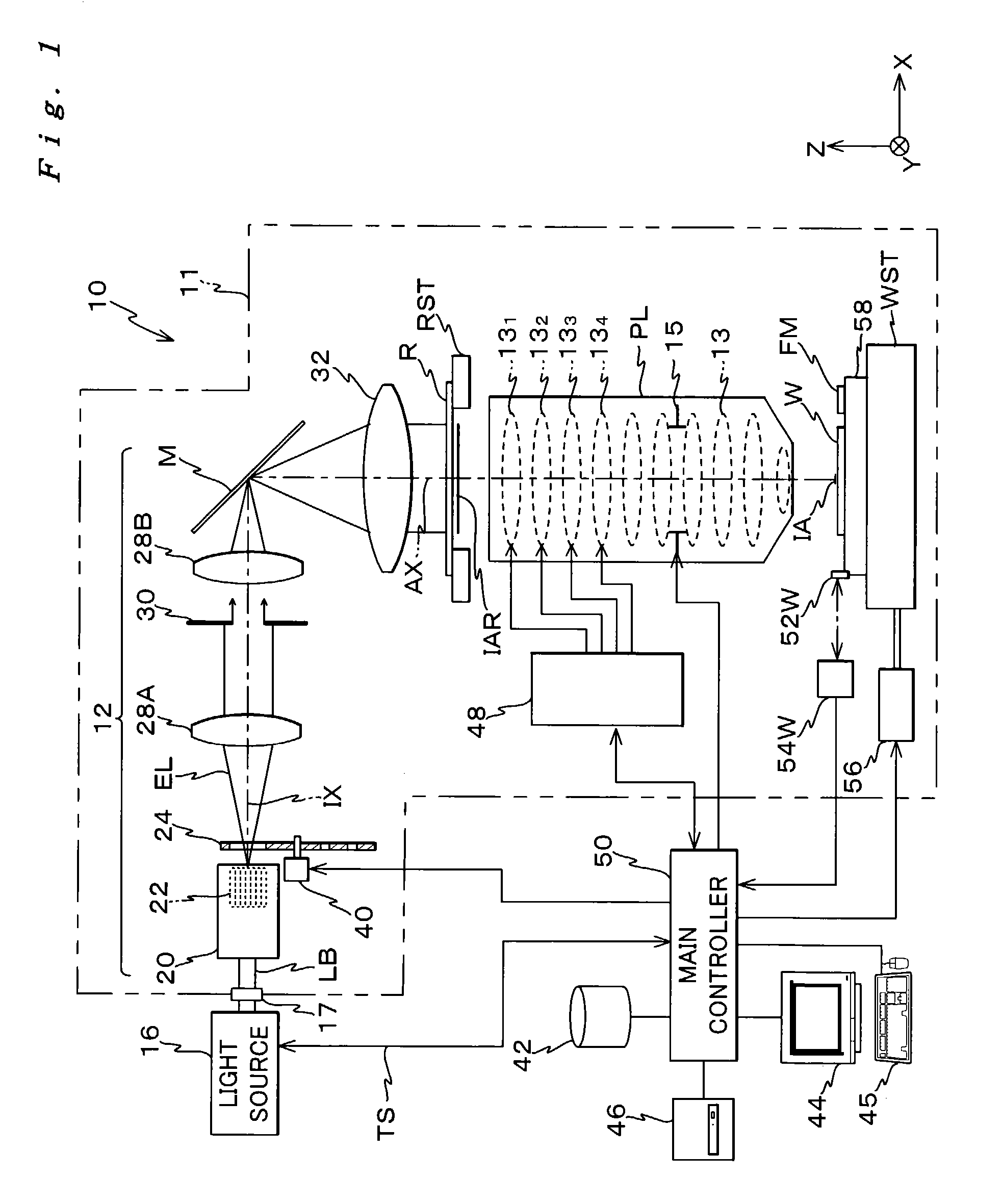
[0104]FIG. 1 shows an entire structure of an exposure apparatus 10 according to an embodiment of the present invention. Exposure apparatus 10 is a reduction projection exposure apparatus based on a step-and-repeat method, or a so-called stepper, which uses a pulse-laser light source as an exposure light source (hereinafter, called a “light source”).

[0105]Exposure apparatus 10 comprises: an illumination system made up of a light source 16 and an illumination optical system 12; a reticle stage RST which serves as a mask stage holding a reticle R serving as a mask, which is illuminated with exposure illumination light EL serving as an energy beam from the illumination system; a projection optical system PL which projects exposure illumination light EL emitted from reticle R onto a wafer W (on the image plane) serving as a substrate; a wafer stage WST serving as a substrate stage on whic...


PUM

PropertyMeasurementUnit
wavelengthaaaaaaaaaa

Abstract

When actual measurement data of a wavefront aberration of a projection optical system is input, a main controller calculates a targeted image forming characteristic of the projection optical system based on the data and a Zernike sensitivity table of the image forming characteristic that is made prior to the input. By using the Zernike sensitivity table, the targeted image forming characteristic can be calculated with only one measurement of wavefront aberration. Moreover, parameters that denote a relation between an adjustment of an adjustable specific optical element and a change in the image forming characteristics of the projection optical system is obtained in advance, and are stored in advance in a storage unit. Then, when the measurement data of the image forming characteristic of the projection optical system is input, the main controller calculates a targeted adjustment amount of the specific optical element using a relation expression between the measurement data, the parameters, and the targeted adjustment amount of the specific optical element, and adjusts the specific optical element based on the calculation results.

Description

CROSS-REFERENCE TO RELATED APPLICATIONS[0001]This is a continuation of International Application PCT / JP01 / 11588, with an international filing date of Dec. 27, 2001, the entire content of which being hereby incorporated herein by reference, which was not published in English.BACKGROUND OF THE INVENTION[0002]1. Field of the Invention[0003]The present invention relates to image forming characteristics measuring methods, image forming characteristics adjusting methods, exposure methods and apparatus, programs and storage mediums, and device manufacturing methods, and more particularly to an image forming characteristics measuring method in which a targeted image forming characteristic of a projection optical system is measured, an image forming characteristics adjusting method in which the image forming characteristic is adjusted, an exposure method in which exposure is performed using a projection optical system whose image forming characteristic has been adjusted according to the imag...

Claims


Application Information

Patent Timeline
Patent Type & Authority Patents(United States)
IPC IPC(8): G01B11/00G01B9/00G01N21/86G03B27/32G03C5/00G02B7/02G02B27/00G03F7/20
CPCG02B7/023G02B27/0043G02B27/0068G03F7/706G03F7/705G03F7/70591G03F7/70258G01M11/00
Inventor TSUKAKOSHI, TOSHIO
Owner NIKON CORP
Why Eureka
Try Eureka