Method for calculating transducer capacitance to determine transducer temperature

a transducer and capacitance technology, applied in the field of ultrasonic surgical systems, can solve the problems of insufficient detection of these particular non-resonant frequencies, inconvenient measurement of csub>0 /sub>, and consuming a considerable amount of time and effort, so as to enhance the overall performance and safety of the system, enhance the speed at which c0 is determined, and reduce the effect of c0 d

Inactive Publication Date: 2006-07-18
ETHICON ENDO SURGERY INC
View PDF25 Cites 713 Cited by
  • Summary
  • Abstract
  • Description
  • Claims
  • Application Information

AI Technical Summary

Benefits of technology

[0027]In a further embodiment of the invention, the temperature of the transducer is determined without the use of temperature sensors. This is accomplished by using non-volatile memory which is embedded in the hand piece to enhance the overall performance and safety of the system. The measured capacitance at an off-resonance frequency (i.e., the shunt capacitance (C0) at a frequency other than resonance) is stored in the non-volatile memory. Linear regression analysis of the values of the transducer capacitance, as it changes with temperature and hand piece use, is also stored in non-volatile memory in the generator.
[0028]Prior to and/or during hand piece activation, the generator performs a “read” of the room temperature capacitance data from the hand piece. The actual capacitance of the hand piece is then measured in accordance with the invention, and the actual transducer temperature is calculated using a polynomial curve stored in the non-volatile memory of the generator. The temperature data is then used to determined whether it is safe to activate the hand piece, as well as to determine what levels of parameters to expect during diagnostic measurements. In this manner, a means to indirectly measure the temperature of the transducer is achieved. In addition, the need f

Problems solved by technology

However, if the resonant frequencies of the blade must first be identified and C0 then measured at non-resonant frequencies, a considerable amount of time and effort will be consumed.
In such a case, the determination of C0 is

Method used


Image

  • Method for calculating transducer capacitance to determine transducer temperature
  • Method for calculating transducer capacitance to determine transducer temperature
  • Method for calculating transducer capacitance to determine transducer temperature

Examples


Embodiment Construction

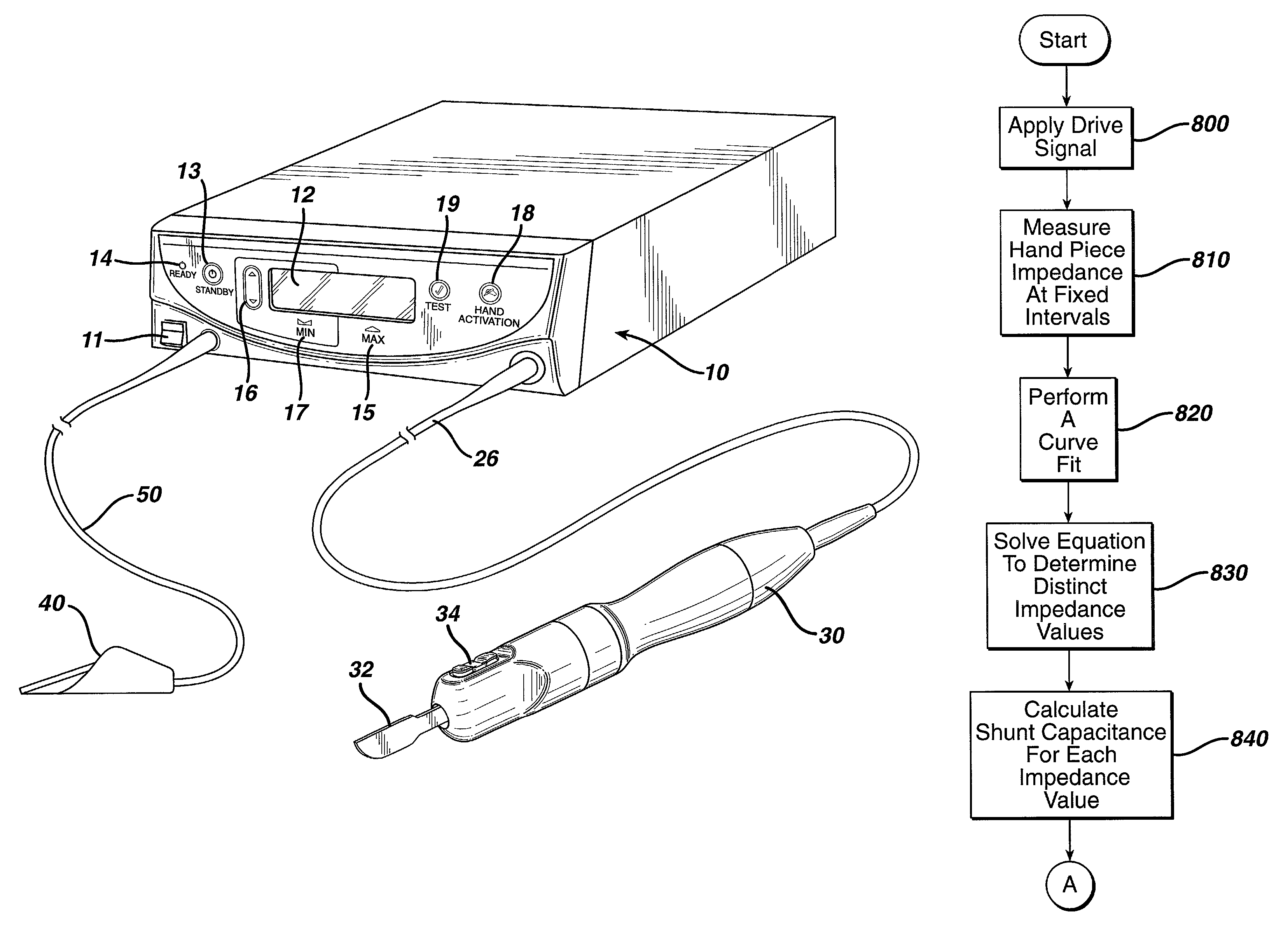
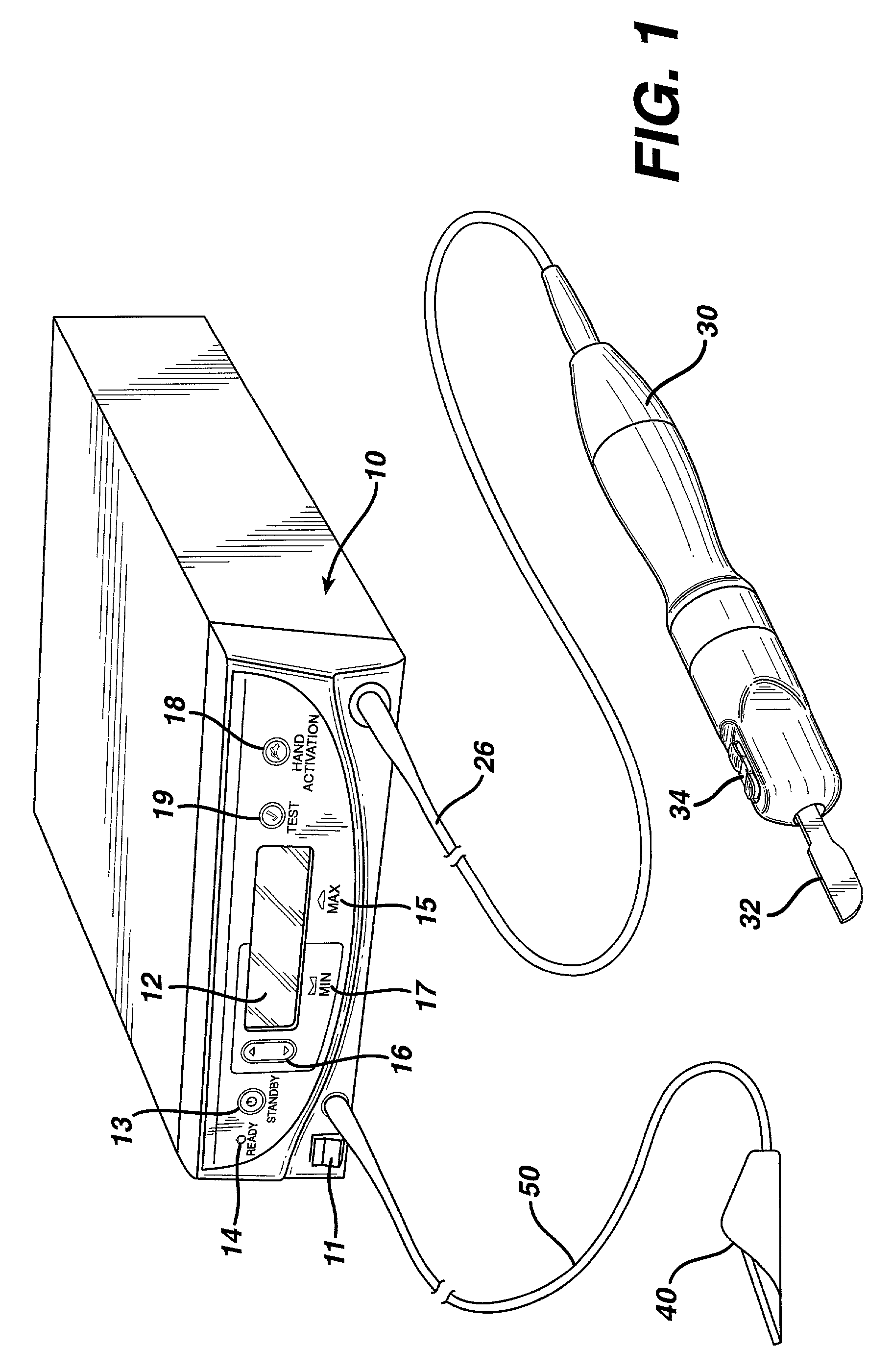
[0040]FIG. 1 is an illustration of a system for implementing the method in accordance with the invention. By means of a first set of wires in cable 26, electrical energy, i.e., drive current, is sent from the console 10 to a hand piece 30 where it imparts ultrasonic longitudinal movement to a surgical device, such as a sharp scalpel blade 32. This blade can be used for simultaneous dissection and cauterization of tissue. The supply of ultrasonic current to the hand piece 30 may be under the control of a switch 34 located on the hand piece, which is connected to the generator in console 10 via wires in cable 26. The generator may also be controlled by a foot switch 40, which is connected to the console 10 by another cable 50. Thus, in use a surgeon may apply an ultrasonic electrical signal to the hand piece, causing the blade to vibrate longitudinally at an ultrasonic frequency, by operating the switch 34 on the hand piece with his finger, or by operating the foot switch 40 with his ...


PUM


Abstract

A method for calculating the capacitance of a transducer (C0) without knowing the exact resonance frequency of a transducer/blade combination is achieved by sweeping across a broad frequency range which contains resonant and non-resonant frequencies where C0 can be measured. A pre-defined frequency range is set independently of the resonance frequency of a specific transducer/blade combination. C0 of the transducer/blade is measured at several different frequencies within the pre-defined frequency range to ensure that invalid C0 measurements are disregarded, and the temperature of the transducer is calculated based on valid C0 measurements. The determined transducer temperature, based on C0 measurements, can be used to optimize performance and/or provide a safety shutdown mechanism for the generator.

Description

RELATED APPLICATIONS[0001]The present invention relates to, and claims priority of, U.S. Provisional Patent Application Ser. No. 60 / 241,891 filed on Oct. 20, 2000, having the same title as the present invention, which is incorporated herein by reference.BACKGROUND OF THE INVENTION[0002]1. Field of the Invention[0003]The present invention generally relates to ultrasonic surgical systems and, more particularly, to a method for determining the temperature of an ultrasonic transducer.[0004]2. Description of the Related Art[0005]It is known that electric scalpels and lasers can be used as a surgical instrument to perform the dual function of simultaneously effecting the incision and hemostatis of soft tissue by cauterizing tissues and blood vessels. However, such instruments employ very high temperatures to achieve coagulation, causing vaporization and fumes as well as splattering. Additionally, the use of such instruments often results in relatively wide zones of thermal tissue damage.[...

Claims


Application Information

Patent Timeline
IPC IPC(8): A61B17/32A61B18/00A61B17/00
CPCA61B17/320068A61B2017/00119A61B2017/00084A61B2017/320069A61B2017/320071A61B2017/320089
Inventor KRAMER, KENNETH S.WIENER, EITAN T.DONOFRIO, WILLIAM T.HOUSER, KEVINSTULEN, FOSTER B.
Owner ETHICON ENDO SURGERY INC
Why Eureka
Try Eureka