
ESP performance optimization control

a technology of electrostatic precipitator and optimization control, which is applied in the direction of electrical supply techniques, transportation and packaging, chemistry apparatus and processes, etc., can solve the problems of back-corona discharge or sparking, insufficient pure dc energization, and accumulation of precipitate layers, etc., to facilitate better collection of fly ash and improve the operational effectiveness of electrostatic precipitator systems.

Inactive Publication Date: 2006-07-25
ELECTRIC POWER RES INST INC
View PDF27 Cites 25 Cited by
  • Summary
  • Abstract
  • Description
  • Claims
  • Application Information

AI Technical Summary

Benefits of technology

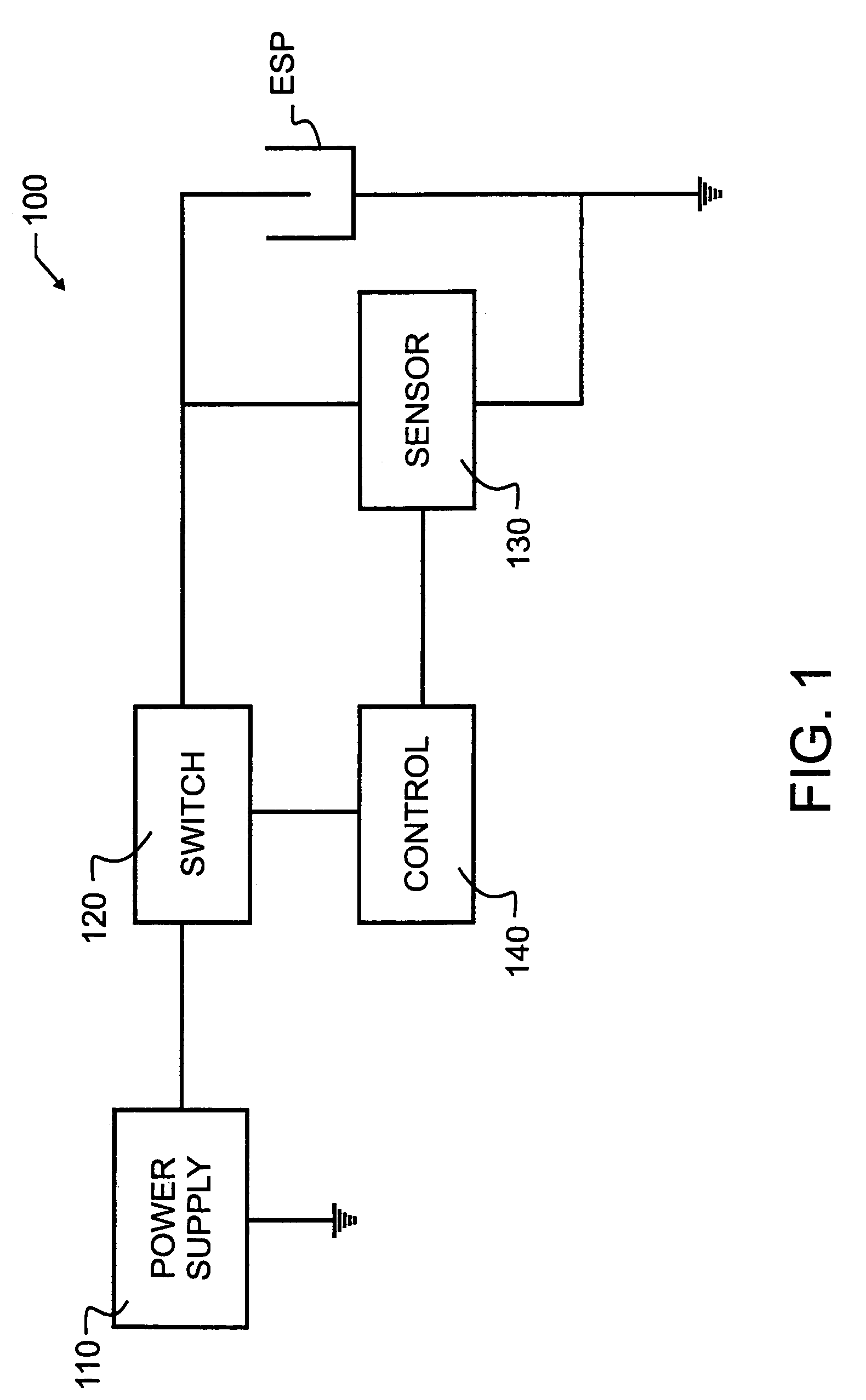
The invention aims to improve the performance of electrostatic precipitator systems by using advanced power supplies to achieve a true state of optimum performance. It also includes monitoring the precipitator for variations in performance and adjusting or modifying control settings accordingly. The invention utilizes readily available electronic components and facilitates better collection of fly ash from coal-fueled electric utility plants.

Problems solved by technology

These features and limitations have dictated application.
Unfortunately, as the particulates precipitate onto the collector plates, a precipitate layer accumulates and increases in thickness.
When a high electric field gradient is created within the precipitate layer, this may lead to a back-corona discharge or sparking.
A problem remains in the powering of electrostatic precipitators to provide control of the precipitator to prevent back-corona or sparking voltages, while at the same time maintaining peak particulate collection efficiency.
However, for the moderate to high resistivity applications identified herein above, such as in low-sulfur coal fired utilities, pure DC energization is not always optimal.
These procedures do not necessarily produce a true state of optimum performance because opacity is not a definitive or sensitive measure of the performance of an individual electric field.

Method used


Image

  • ESP performance optimization control
  • ESP performance optimization control
  • ESP performance optimization control

Examples


example 1

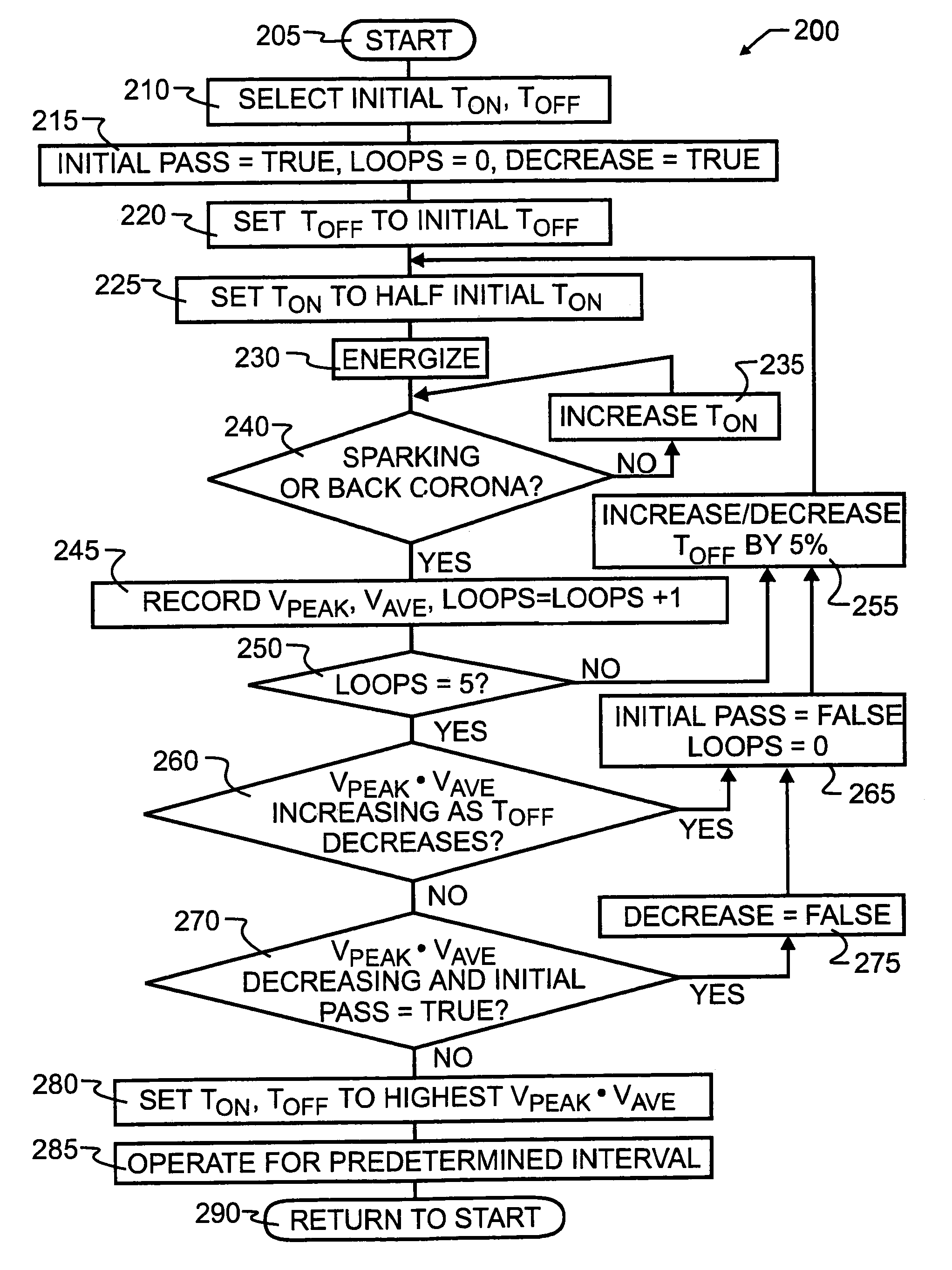
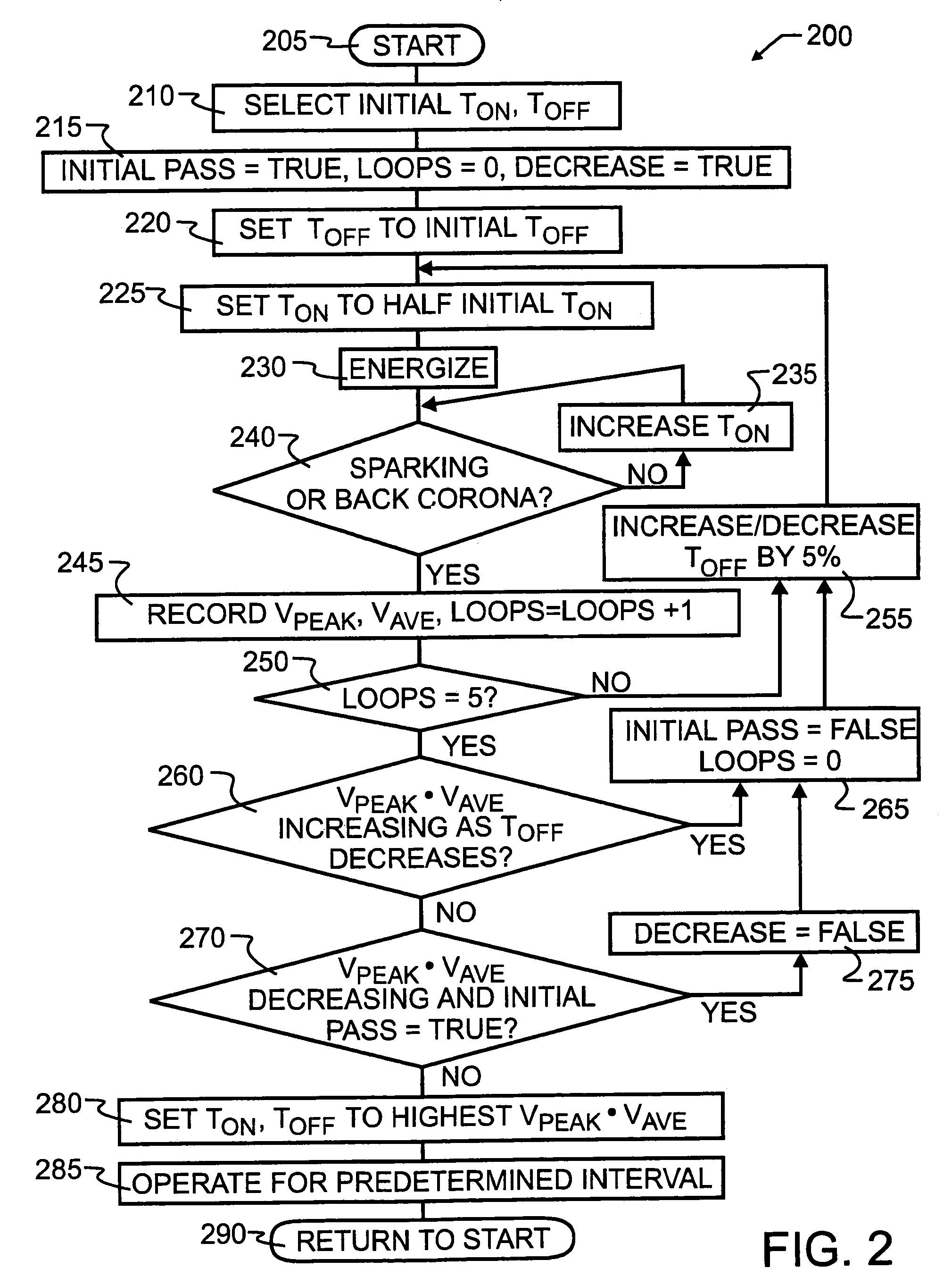
Intermittent Energization Self-Tuning Algorithm for Optimizing Peak Times Average in ESP Application

Steps to Achieving Self-Tuning:

[0047]Please note that the program may run each of the following steps multiple times (loop through numerous times) and use an average value (for any given step) to minimize the possibility of improper self-tuning due to sporadic operation of the esp.[0048]1. On initial turn-on of the high voltage, establish the voltage at which corona onset starts (Vco) and the voltage at which spark-over of the esp field occurs (Vsp). If no spark occurs, the voltage limit level becomes Vsp.[0049]2. The next step is to establish the value require for Toff. This is done by[0050]2.1 Ramping the voltage to K2*Vsp (where K2 is 80 to 95%) and letting the voltage decay until it reaches Vco. The value of Toff at this point becomes Toff—initial.[0051]2.2 The voltage is then turned back on again until K2*Vsp is reached; this time the voltage is allowed to decay for Toff=K3*Toff—...

example 2

Peak Times Average Algorithms

[0068]1. Determine corona onset voltage, sparking voltage, and the time (Ton initial) to go from corona onset to sparking voltage with full power on and the time (Toff initial) to drift from just below sparking voltage to corona onset voltage. Go to step 2.[0069]2. Pick initial Ton, which is slightly less than Ton initial (say 0.95 Ton initial). Go to step 3.[0070]3. Pick initial Toff (say Toff initial). Go to step 4.[0071]4. Starting with this Ton and Toff keeping reducing Toff until sparking occurs. Go to step 5.[0072]5. Increase Toff slightly (say Toff=1.05 Toff at spark). Go to step 6.[0073]6. Operate long enough with this Ton and Toff to determine Vpk and Vaverage and record these numbers and their product. Go to step 7.[0074]7. Decrease Ton slightly (say by 5%). Go to step 8.[0075]8. Repeat steps 3 through 7 until TON=0.05 TON INITIAL or until back corona occurs for the shortest TOFF. When TON=0.05 TON INITIAL or when back corona occurs for the sho...


PUM


Abstract

A gas separation apparatus which uses electrostatic precipitators and a DC power supply is controlled to optimally remove moderate to high resistivity ash. The DC power supply is pulse width modulated to maximize the product of the peak electric field and the average electric field. The method used to optimize operation includes selecting initial on and off times for the power supply, operating the power supply using the initial off and on times, and progressively decreasing the off time. A determination is made whether the off time may be further decreased. Ultimately, the on and off time intervals that produce the highest peak and average voltage are determined, and the system is operated using these parameters. A procedure may be periodically repeated to monitor the process and detect if there has been a change in the system that would require new time intervals. The novel separation apparatus and control method offer particular synergy when applied to the effluent stream from a coal-fired electric power plant or other similar gas streams.

Description

BACKGROUND OF THE INVENTION[0001]1. Field of the Invention[0002]This invention pertains generally to gas separation processes. More specifically, the present invention uses voltage sensing techniques to optimize performance of an electrostatic precipitator. In a most specific manifestation, a novel method is provided which maximizes the product of the electric field at the collector plate and the charge of the particles being collected.[0003]2. Description of Related Art[0004]Industries as diverse as mills, pharmaceutical or chemical, food processing, and cement kilns must separate contaminants or particulates from an air or gaseous stream. The gases may be a product of combustion, such as present in an exhaust stack, but may also represent other gas streams and may contain such diverse materials as liquid particulates, smoke or dust from various sources, and the like. Separators that must process relatively large volumes of gas are common in power generating facilities and factorie...

Claims


Application Information

Patent Timeline
Patent Type & Authority Patents(United States)
IPC IPC(8): B03C3/68
CPCB03C3/68Y10S323/903
Inventor ALTMAN, RALPH F.GUENTHER, ROBERT N.
Owner ELECTRIC POWER RES INST INC
Learn More