Motor control apparatus

a technology of motor control and control apparatus, which is applied in the direction of motor/generator/converter stopper, dynamo-electric converter control, instruments, etc., can solve the problems of preventing the generation of torque that drives the rotor in the reverse rotation direction, and reducing the time taken to return the rotation direction from the reverse direction to the normal direction

Active Publication Date: 2006-08-01
DENSO CORP
View PDF23 Cites 36 Cited by
  • Summary
  • Abstract
  • Description
  • Claims
  • Application Information

AI Technical Summary

Benefits of technology

[0018]From this time onward, the rotor rotates in synchronism with the current supply phase switching and pulse output signals are output from the encoder in synchronism with the rotation of the rotor. Therefore, an angle (i.e., a rotation amount) by which the rotor has rotated actually in synchronism with the current supply phase switching until the end of the initial drive is recognized by checking an encoder count of the output signals of the encoder at the end of the initial drive, whereby a corresponding relationship between the encoder count, a rotation position of the rotor, and a current supply phase at the end of the initial drive can be recognized. Learning this corresponding relationship makes it possible to rotate the motor normally by selecting a correct current supply phase in a subsequent ordinary drive on the basis of a count of the output signals of the encoder and a learning result at the end of the initial drive.
[0019]According to a second aspect of the invention, in rotating the rotor to a target position on the basis of the encoder count, the variation direction of the encoder count is monitored and it is determined whether the rotation direction of the rotor has reversed from the rotation direction toward the target position. If reversing is detected, current supply for phases with which the rotor is driven in the reverse direction is prohibited. With this measure, even if the rotation direction of the rotor is reversed due to some inexorability and the variation direction of the encoder count is thereby reversed while the rotor is rotated to a target position on the basis of the encoder count, generation of torque that drives the rotor in the reverse rotation direction can be prevented. Therefore, the time taken to return the rotation direction from the reverse direction to the normal direction can be shortened. A stable position switching control (positioning control) is enabled.
[0021]As described above, a feedback control start position stopping and holding process is executed immediately before the start of a feedback control, whereby the rotor is kept at a position where the preceding feedback control finished. Therefore, even if the position of the rotor deviated in a period when the rotor should be stopped, the rotor can be positioned at a proper position at the start of a feedback control. As a result, at the start of the feedback control, the position of the rotor and the current supply phase can reliably be synchronized with each other from the first current supply phase. It becomes possible to prevent a loss of synchronization and prevent the rotor from rotating away from a target position at the start of the feedback control, to allow the rotor to reliably rotate to the target position with a stable feedback control, and to perform a position switching control (positioning control) that is highly stable and reliable.
[0023]According to a fifth aspect of the invention, the phase lead of the current supply phase with respect to the rotation phase of the rotor is corrected in accordance with the rotation speed of the rotor. Starting torque can be increased by decreasing the phase lead of the current supply phase at a start of driving, whereby the rotation speed of the rotor can be raised quickly. Since the phase lead of the current supply phase is corrected so as to increase as the rotation speed of the rotor increases, a synchronized relationship between the generation of torque of the current supply phase and the actual rotation phase of the rotor can be maintained even during high-speed rotation, which makes it possible to rotate the rotor stably at high speed. Superior starting performance and superior high-speed rotation performance can thus be attained simultaneously.
[0024]According to a sixth aspect of the invention, a target position is stored in a nonvolatile memory. At starting, the target position stored in the nonvolatile memory is set as a target position of starting. With this measure, even if the controller (e.g., a microcomputer) of the motor is reset for a certain reason, at subsequent starting a target value that is stored in the nonvolatile memory immediately before the resetting is set as a target value of starting. Therefore, target value data are not changed in association with the resetting, which prevents a control object from being rotated to an unintended position.
[0025]According to a seventh aspect of the invention, a first current supply phase is set on the basis of an encoder count in synchronism with output of a pulse of an output signal of the encoder during a drive control on the motor. A second current supply phase is set on the basis of the encoder count in a prescribed cycle until the rotor reaches a target position. Every time a first or second current supply phase is set, the a winding of the thus-set current supply phase is energized.

Problems solved by technology

Therefore, the motor cannot be driven normally unless a corresponding relationship between the rotor rotation position and the current supply phase is obtained by detecting the absolute rotation position of the rotor by a certain method after the application of power.
However, mere simultaneous two-phase current supply at the beginning of a starting period not always causes the rotor to rotate to a position corresponding to the two current supply phases; there may occur a case that a corresponding relationship between the rotor rotation position and the current supply phase is not obtained.
However, producing lower torque than two-phase current supply does, one-phase current supply may not be sufficient for the rotor to rotate to a corresponding position.
Therefore, merely effecting one-phase current supply first may not eliminate an unstable region that will be caused by two-phase current supply, and a reference position of the rotor may still be learned erroneously.
This raises a problem that long time is needed to return the rotation direction from the reverse direction to the normal direction; the rotor may reach a target position with a long delay or, in the worst case, it may become impossible to stop the reverse rotation, that is, the motor may become uncontrollable.
However, in this configuration, if the rotor is stopped for a long time, the winding of the same phase continues to be energized for a ling time and hence may overheat and burn.
However, where the rotor is not energized while it is stopped, there is no electromagnetic force for keeping the rotor at a target position (i.e., a position when the rotor stopped) and hence the rotor may deviate from the target position.
However, even with this measure, the rotor may still deviate from the target position due to play amount in the stopping and holding mechanism, its variations in manufacture, or the like.
In this case, the rotor may not be rotated normally to a target position; for example, a loss of synchronization occurs at the start of the feedback control to cause a failure of starting or the rotor is rotated away from the target position.
Therefore, even if the deviation of the rotor is so small that its position stays within a range corresponding to a count of the encoder, a loss of synchronization may still occur at the start of a feedback control to cause a failure of starting if the feedback control is started after current supply is effected for A-phase for which current supply should be effected first and before the rotor is moved to a position for current supply and kept there.
However, play amount due to backlash, clearances, etc. exists between constituent parts of the rotation transmission system.
Therefore, even if the rotation amount of the motor can be controlled correctly on the basis of the count of the encoder, an error corresponding to the play amount in the rotation transmission system occurs in the manipulated variable for the control object and hence the manipulated variable for the control object cannot be controlled accurately.
However, torque is generated actually with a delay corresponding to the inductance of the winding of a current supply phase from a start of current supply of the winding.
Therefore, if the rotation speed of the rotor is too high, the rotor rotates by a considerable angle from a start of current supply of the current supply phase winding to actual torque generation, that is, the generation of torque of the current supply phase delays from the actual rotation phase of the rotor.
However, if the phase lead of the current supply phase is large at a start of driving (i.e., at starting), the starting torque becomes low and the starting of the motor becomes unstable or results in a failure.
Further, if the phase lead of the current supply phase is set large and the rotation speed of the rotor is thereby increased, the rotor tends to pass a target position due to inertia at an end of driving (occurrence of an overshoot), that is, it is difficult to stop the rotor at the target position correctly.
However, if this is done by one-phase current supply that produces low position-keeping torque, the rotor vibrates and cannot be stopped completely at each position.
As such, resetting of the microcomputer may cause a problem that a control object is switched contrary to the intention so as to be directed to an unintended position.
Therefore, if the rotation of the rotor is stopped for a certain reason during a feedback control and the output of the pulse signal from the encoder is also stopped, the current supply phase switching can no longer be performed.
This means a problem that the rotor cannot be rotated to a target position.

Method used


Image

  • Motor control apparatus
  • Motor control apparatus
  • Motor control apparatus

Examples


first embodiment

[0079]A first embodiment in which the present invention is applied to a position switching device of a vehicle will be hereinafter described with reference to FIGS. 1–48.

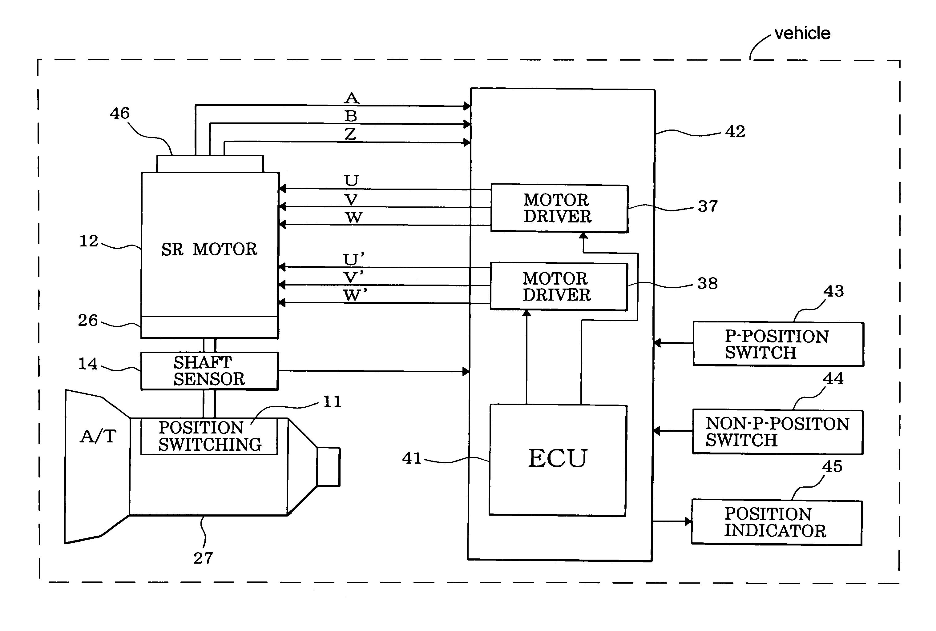
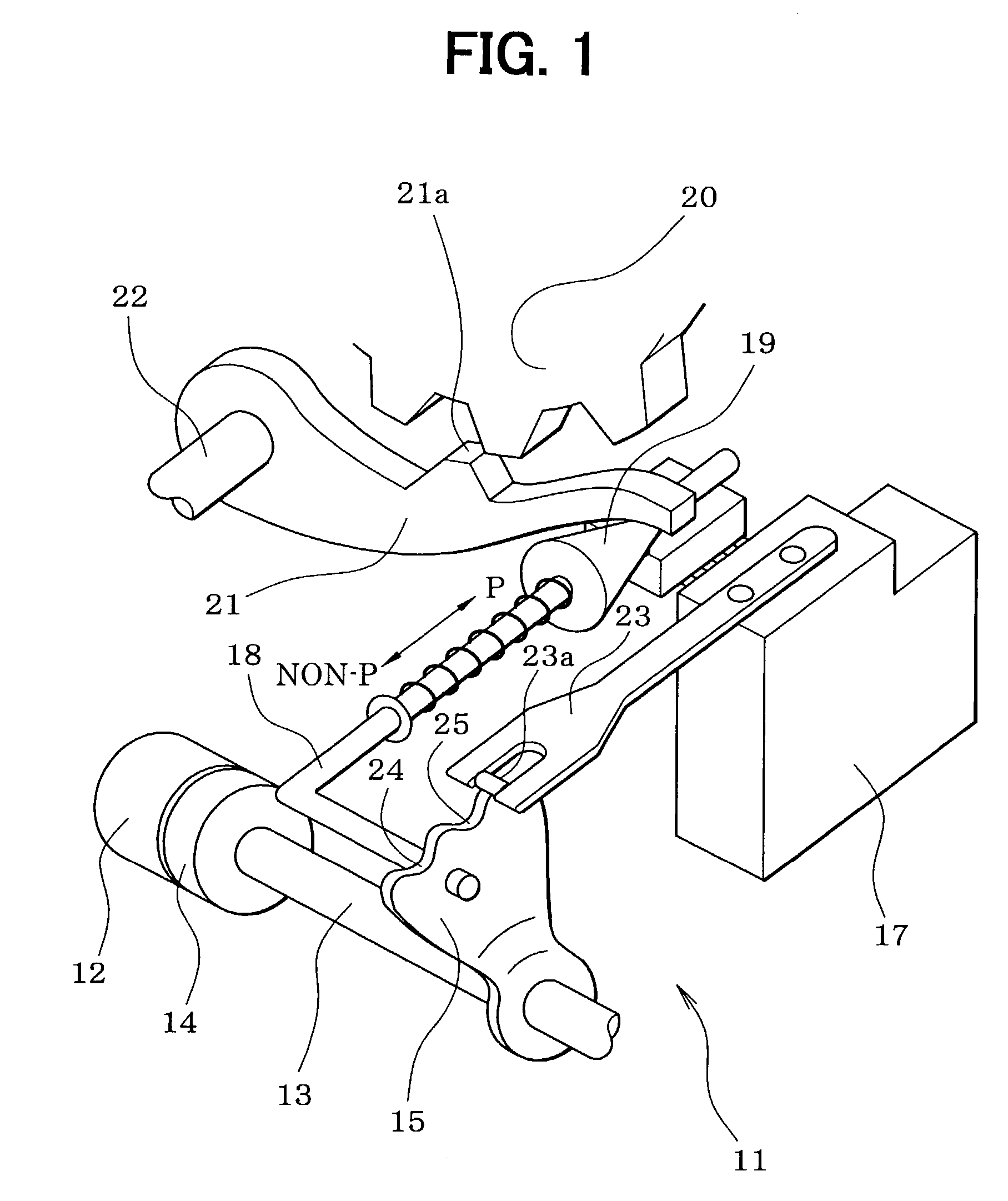
[0080]First, the configuration of a position switching mechanism 11 will be described with reference to FIG. 1. A motor 12 as a drive source of the position switching mechanism 11 is a switched reluctance motor, for example, incorporates a speed-reducing mechanism 26 (see FIG. 4), and is equipped with an output shaft sensor 14 for detecting a rotation position of the output shaft 13 of the speed-reducing mechanism 26. A detent lever 15 is fixed to the output shaft 13.

[0081]An L-shaped parking rod 18 is fixed to the detent lever 15. A conical body 19 that is provided at the tip of the parking rod 18 is in contact with a lock lever 21. The lock lever 21 is moved in the vertical direction in accordance with the position of the conical body 19 and thereby locks or unlocks a parking gear 20. The parking gear 20 is attach...

second embodiment

[0386]In the above first embodiment, with attention paid to the fact that the output shaft sensor 14 for detecting a rotation position of the output shaft 13 of the SR motor 12 (i.e., an actual shift position) is provided, an actual shift position that is detected by the output shaft sensor 14 at starting (e.g., after resetting of the CPU of the ECU 41 or after power application to it) is set as an instructed shift position sft of starting. Where the output shaft sensor 14 is not provided, it is appropriate to set an instructed shift position sft of starting as in a second embodiment of the invention shown in FIGS. 49 and 50. It goes without saying that the instructed shift position setting method according to the second embodiment may be applied to a system that is provided with the output shaft sensor 14.

[0387]In the second embodiment, a latest instructed shift position sft is stored in the nonvolatile memory such as an SRAM of the ECU 41 while the vehicle is driven. At starting (...

third embodiment

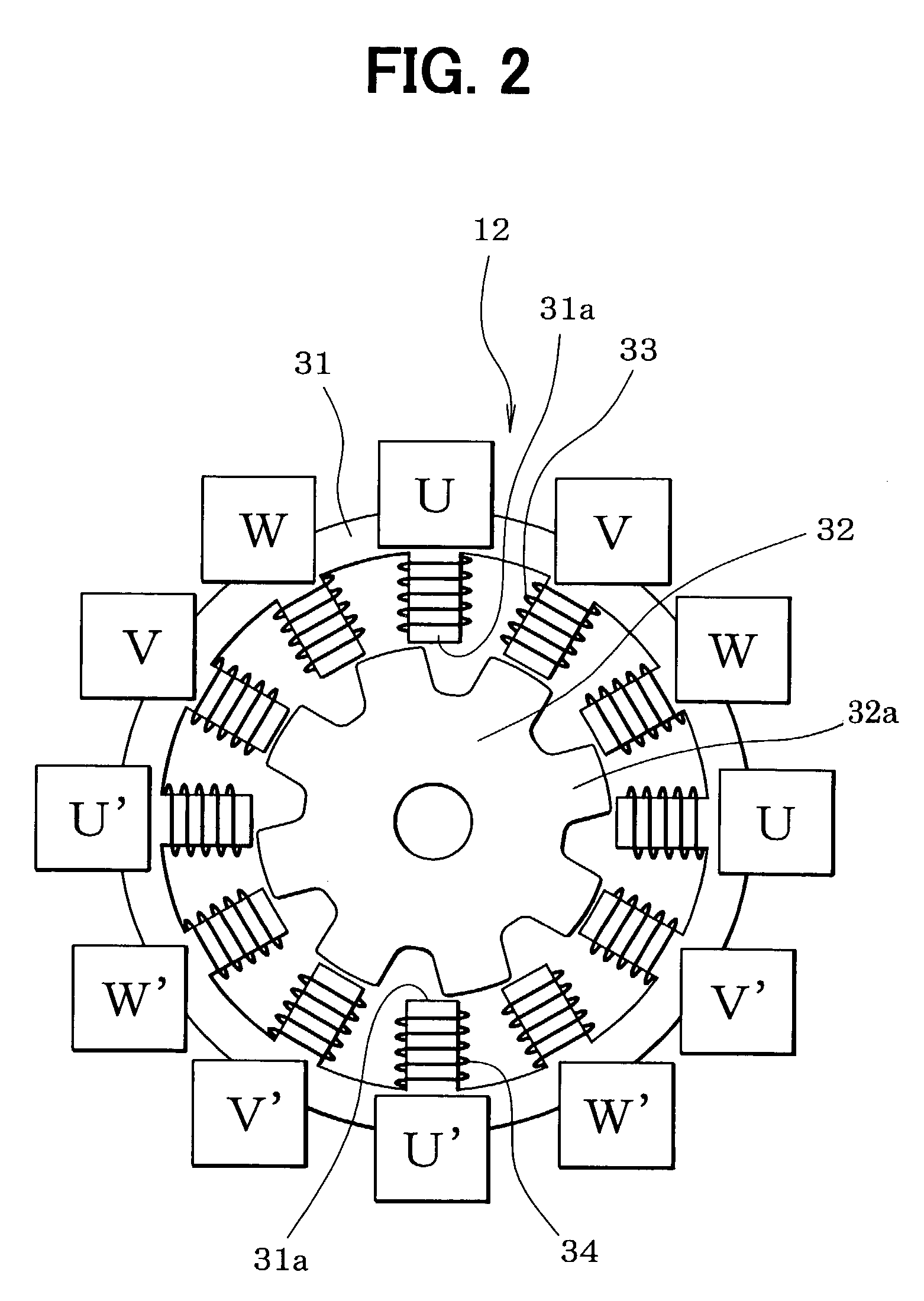
[0401]During rotation of the SR motor 12, as shown in FIG. 52, the encoder 46 outputs an A-phase signal pulse and a B-phase signal pulse alternately in synchronism with the rotation of the rotor 32 and also outputs a Z-phase signal pulse every time current supply is effected for all the phases around and the rotor 32 is rotated by 45°. Since reference rotation positions of the rotor 32 can be detected correctly by using the Z-phase signal, whether the corresponding relationship between the rotation position of the rotor 32 and the current supply phase (i.e., encoder count) is not deviated from a correct one can be checked by determining whether a current supply phase (i.e., encoder count) with which a Z-phase signal pulse is output corresponds to a reference rotation position of the rotor 32. A highly reliable motor control can be performed by performing, if a deviation from the correct relationship is found, a Z-phase correction for correcting for the deviation.

[0402]The Z-phase co...


PUM


Abstract

In an automatic transmission position control by a motor, it is determined whether the present instant belongs to a starting period, that is, the present instant is immediately after resetting of a control unit or application of power to it. If it is the starting period, an actual shift position that is detected from an output of an output shaft sensor for detecting a rotation position of a motor is set as an instructed shift position. With this measure, even if the control unit is reset for a certain reason while the vehicle is running, the instructed shift position is not changed in association with the resetting. This prevents trouble that the shift position is switched contrary to the intention of the driver, whereby the reliability of a position switching control can be increased.

Description

CROSS REFERENCE TO RELATED APPLICATION[0001]This application is based on and incorporates herein by reference Japanese Patent Applications No. 2002-161849 filed on Jun. 3, 2002, No. 2002-175377 filed on Jun. 17, 2002, No. 2002-175378 filed on Jun. 17, 2002, No. 2002-177738 filed on Jun. 18, 2002, No. 2002-177739 filed on Jun. 18, 2002, No. 2002-207560 filed on Jul. 16, 2002, and No. 2002-276521 filed on Sep. 24, 2002.FIELD OF THE INVENTION[0002]The present invention relates to a motor control apparatus for rotationally driving (rotating) the rotor of a motor by sequentially switching the current supply phase of the motor on the basis of an output signal of an encoder.BACKGROUND OF THE INVENTION[0003]Among brushless motors such as switched reluctance motors the demand for which has increased recently because they are inexpensive and simple in structure are ones that incorporate an encoder for outputting a pulse signal in synchronism with the rotation of the rotor and in which the rot...

Claims


Application Information

Patent Timeline
Patent Type & Authority Patents(United States)
IPC IPC(8): H02P1/46H02P23/00H02P25/00H02P3/18H02P6/00H02P8/42
CPCF16H61/32H02P8/42H02P25/08H02P25/085H02P25/082Y10T74/2003F16H2061/326H02P25/0925H02P25/092
Inventor NAKAI, YASUHIROKAMIO, SHIGERU
Owner DENSO CORP
Why Eureka
Try Eureka