
Harmonic mixer

a mixer and mixer stage technology, applied in the field of transceivers, can solve the problems of low mixer stage linearity, carrier leakage, etc., and achieve the effect of reasonable improvement of the hardness of the vco signal in relation to the signal coming from the power amplifier

Inactive Publication Date: 2006-08-01
MEDIATEK INC
View PDF10 Cites 22 Cited by
  • Summary
  • Abstract
  • Description
  • Claims
  • Application Information

AI Technical Summary

Benefits of technology

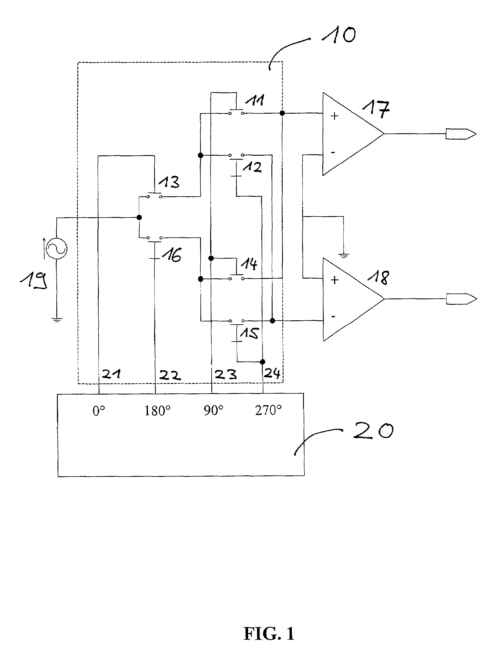
[0023]As can be seen from (1), for a phase shift of φ=90 degrees between the two VCO signals, the DC component gets cancelled. This simplifies the circuit design.
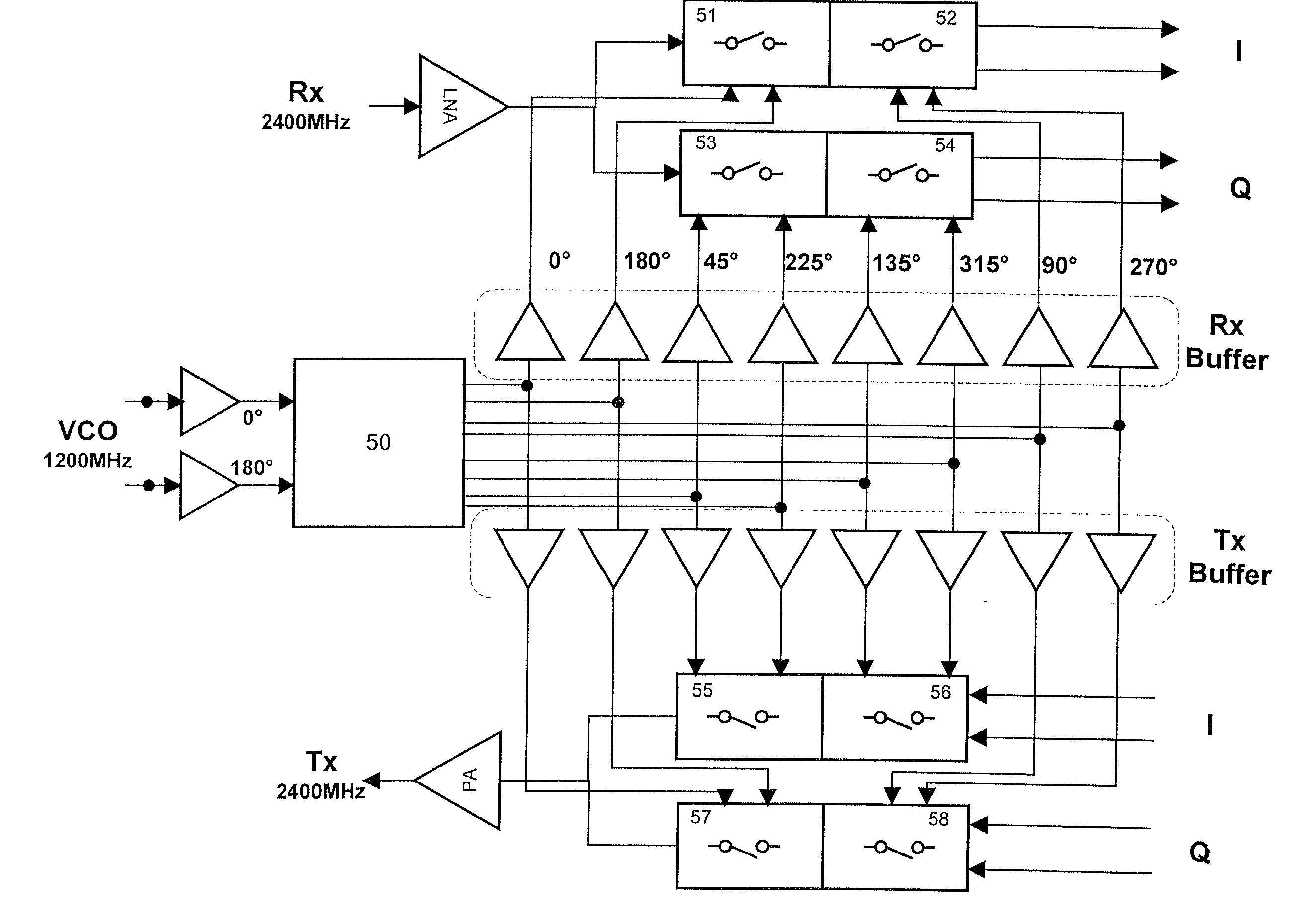
[0027]The present invention solves an inherent problem of mixer realization for direct up- and down-conversion architectures, whereby no other implementation leads to such performance with respect to linearity and suppression of LO signals. Furthermore, from a system architecture point of view, the hardness of the VCO signals in relation to the signals coming from the power amplifier is reasonably improved.

Problems solved by technology

Generally, it is difficult to integrate high-Q filters.
For such direct conversion topologies, several problems like carrier leakage, second order intermodulation, and interference between local oscillator and RF signals exist.
Especially direct conversion receivers require a high degree of linearity of the mixer stage, since second order spurious products fall directly into the obtained baseband frequency and disturb the desired signal.
Generally, this will lead to signal self-mixing effects causing DC (direct current) offset.
However, this DC offset is not constant.
Further problems in state of the art transceiver architectures are pulling effects.
However, isolation is a problem for architectures where the VCO is operating at the transmit frequency, i.e., FM (frequency modulation) systems using direct modulation of the VCO or a direct up-conversion principle.
The same problem occurs if strong signals are applied to the Rx (receive) input.
These spurious signals are especially disadvantageous for the direct conversion principle, since the desired down-converted RF signal is also centered at a frequency of f=0.

Method used


Image

  • Harmonic mixer
  • Harmonic mixer
  • Harmonic mixer

Examples


Embodiment Construction

[0039]Illustrative embodiments of the invention are described below. In the interest of clarity, not all features of an actual implementation are described in this specification. It will of course be appreciated that in the development of any such actual embodiment, numerous implementation-specific decisions must be made to achieve the developers' specific goals, such as compliance with system-related and business-related constraints, which will vary from one implementation to another. Moreover, it will be appreciated that such a development effort might be complex and time-consuming, but would nevertheless be a routine undertaking for those of ordinary skill in the art having the benefit of this disclosure.

[0040]The present invention will now be described with reference to the attached figures. Although the various regions and structures of a semiconductor device are depicted in the drawings as having very precise, sharp configurations and profiles, those skilled in the art recogni...


PUM


Abstract

The invention provides a harmonic direct conversion mixer having a multiplier circuit comprising first and second mixers and a generator for generating two first and two second control signals for controlling the first and second mixers. The control signals are balanced signals and are provided in four phases shifted by π / 2 in phase. The frequency of the control signals is different from the frequency of the mixer input signal.

Description

BACKGROUND OF THE INVENTION[0001]1. Field of the Invention[0002]This invention relates generally to transceivers, and, more particularly, to a harmonic mixer useful in an integrated radio frequency transceiver.[0003]2. Description of the Related Art[0004]The increasing demand for portable wireless communication devices having low price, weight and size and improved capabilities is prompting research in new IC (integrated circuit) technologies, circuit configurations and transceiver architectures. Transceiver implementations for wide band systems comprising direct conversion mixers are known and meet the above mentioned requirements better than architectures based on the widely used super-heterodyne principle.[0005]At the transmitter stage of the transceiver, direct conversion mixers are used to up-convert a baseband analog or digital signal to a RF (radio frequency) signal for ease of transmission. At the receiver stage, direct conversion mixers are used to down-convert a received R...

Claims


Application Information

Patent Timeline
Patent Type & Authority Patents(United States)
IPC IPC(8): H04B1/26H04B1/10H03D1/00H04L27/06H03B21/01H03D7/14H04L27/20H04L27/36
CPCH03B21/01H03D7/1433H03D7/1441H03D7/165H03D7/1466H03D7/1475H03D7/1491H03D7/1458H03D7/14
Inventor KLUGE, WOLFRAMEGGERT, DIETMAR
Owner MEDIATEK INC
Learn More