Apparatus for enhancing thermal stability, improving biasing and reducing damage from electrostatic discharge in self-pinned abutted junction heads having a first self-pinned layer extending under the hard bias layers

a junction head and self-pinned technology, applied in the field of magnetic sensors, can solve the problems of increasing structure resistance, affecting the accuracy of measurement results, so as to improve biasing, enhance thermal stability, and reduce damage

Inactive Publication Date: 2006-08-15
HITACHI GLOBAL STORAGE TECH NETHERLANDS BV
View PDF23 Cites 19 Cited by
  • Summary
  • Abstract
  • Description
  • Claims
  • Application Information

AI Technical Summary

Benefits of technology

[0016]To overcome the limitations in the prior art described above, and to overcome other limitations that will become apparent upon reading and understanding the present specification, the present invention discloses a method and apparatus for enhancing thermal stability, improving biasing and reducing damage from electrostatic discharge in self-pinned abutted junction heads.
[0017]The present invention solves the above-described problems by providing a first layer of a self-pinned layer having its ends disposed under the hard bias layers to provide electrostatic discharge protection and thermal stability. The free layer is located in a central region and its pinning is maintained by the hard bias layers.

Problems solved by technology

This causes an increase in the structure's resistance.
However, the longitudinal schemes discussed above are sensitive to electrostatic discharge (ESD) and high temperatures produced thereby.
Damage to a sensor form ESD occurs in different levels.
If the energy level is high enough, ESD will burn and / or melt GMR stripes resulting in bumps on an air-bearing surface (ABS).
For example, high ESD energy absorbed at the two ends of an abutted junction of a MR sensor may form bumps, including fractured stripes between the bumps, on the sensor.
Hence, the added energy from ESD can physically damage the sensor and / or cause unpinning of a pinned layer.
A self-pinned LOL is less sensitive to ESD than the self-pinned abutted junction head, however the LOL head does not provide a desired narrow trackwidth, e.g., below 0.15 um.

Method used


Image

  • Apparatus for enhancing thermal stability, improving biasing and reducing damage from electrostatic discharge in self-pinned abutted junction heads having a first self-pinned layer extending under the hard bias layers
  • Apparatus for enhancing thermal stability, improving biasing and reducing damage from electrostatic discharge in self-pinned abutted junction heads having a first self-pinned layer extending under the hard bias layers
  • Apparatus for enhancing thermal stability, improving biasing and reducing damage from electrostatic discharge in self-pinned abutted junction heads having a first self-pinned layer extending under the hard bias layers

Examples


Embodiment Construction

[0037]In the following description of the exemplary embodiment, reference is made to the accompanying drawings, which form a part hereof, and in which is shown by way of illustration the specific embodiment in which the invention may be practiced. It is to be understood that other embodiments may be utilized as structural changes may be made without departing from the scope of the present invention.

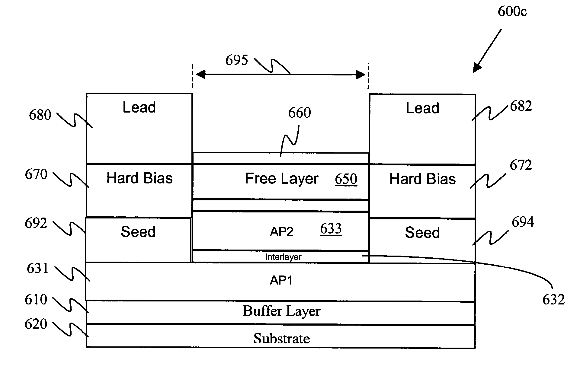
[0038]The present invention provides a method and apparatus for enhancing thermal stability, improving biasing and reducing damage from electrostatic discharge in self-pinned abutted junction heads. A first layer of a self-pinned layer is formed having its ends disposed under the hard bias layers to provide electrostatic discharge protection and thermal stability. The free layer is located in a central region and its pinning is maintained by the cooler hard bias layers.

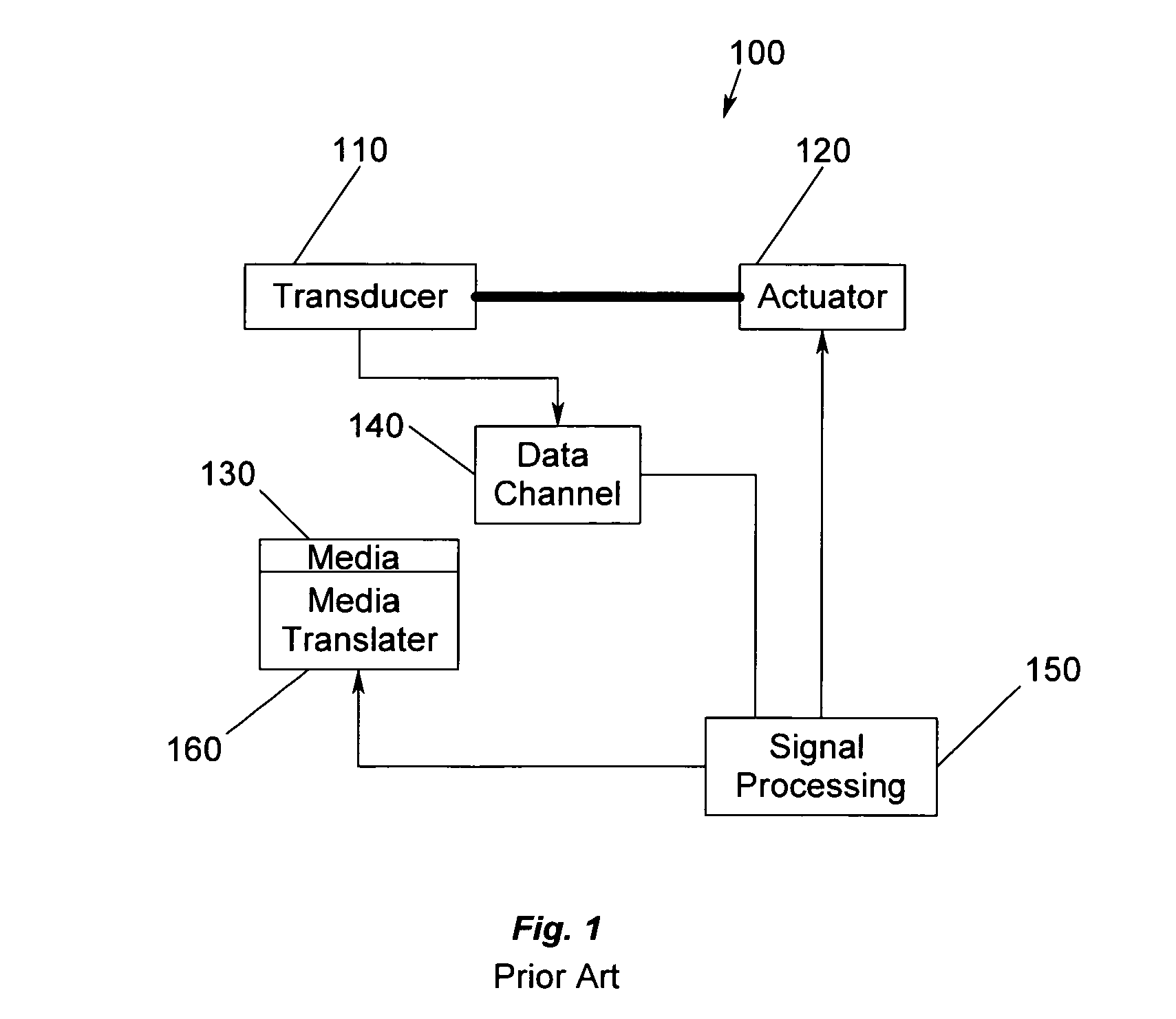
[0039]FIG. 1 illustrates a storage system 100. In FIG. 1, a transducer 110 is under control of an actuator 120. The actua...


PUM

PropertyMeasurementUnit
magneticaaaaaaaaaa
hard biasaaaaaaaaaa
hardaaaaaaaaaa

Abstract

A method and apparatus for enhancing thermal stability, improving biasing and reducing damage from electrical surges in self-pinned abutted junction heads. A first self-pinned layer having a first magnetic orientation is provided, wherein the first self-pinned layer has a first end, a second end and central portion. A second self-pinned layer is formed over only the central portion of the first self-pinned layer and an interlayer is disposed between the first and second self-pinned layers. A free layer is formed in a central region over the second self-pinned layer. First and second hard bias layers are formed over the first and second ends of the first self-pinned layer respectively, the first and second hard bias layer abutting the free layer, the first and second end of the first self-pinned layer extending under the hard bias layers at the first and second ends.

Description

BACKGROUND OF THE INVENTION[0001]1. Field of the Invention[0002]This invention relates in general to magnetic sensors, and more particularly to a method and apparatus for enhancing thermal stability, improving biasing and reducing damage from electrostatic discharge in self-pinned abutted junction heads.[0003]2. Description of Related Art[0004]Magnetic recording is a key and invaluable segment of the information-processing industry. While the basic principles are one hundred years old for early tape devices, and over forty years old for magnetic hard disk drives, an influx of technical innovations continues to extend the storage capacity and performance of magnetic recording products. For hard disk drives, the areal density or density of written data bits on the magnetic medium has increased by a factor of more than two million since the first disk drive was applied to data storage. Areal density continues to grow due to improvements in magnet recording heads, media, drive electroni...

Claims


Application Information

Patent Timeline
Patent Type & Authority Patents(United States)
IPC IPC(8): G11B5/39G11B5/127G11B5/33H01F10/32H01F41/30
CPCB82Y10/00B82Y25/00B82Y40/00H01F41/302G11B5/3932G11B5/3903H01F10/3281
Inventor GILL, HARDAYAL SINGHHSIAO, WEN-CHIENLUO, JIH-SHIUAN
Owner HITACHI GLOBAL STORAGE TECH NETHERLANDS BV
Why Eureka
Try Eureka