Superconducting cable joint structure

Inactive Publication Date: 2006-08-22
SUMITOMO ELECTRIC IND LTD +1
View PDF16 Cites 12 Cited by
  • Summary
  • Abstract
  • Description
  • Claims
  • Application Information

AI Technical Summary

Benefits of technology

[0007]The present invention contemplates jointing and thus connecting together cores of superconducting cables, respectively, while preventing a connection fro

Problems solved by technology

Currently, cities and the like have a tendency to consume increasing amounts of power, and accordingly require larger underground power transmission capacities.
Currently, however, there has not been a method proposed to suitably joint a superconducting cable currently being studied.
As a result, an increased quantity of heat is generated and a coolant surrounding the cable cores may bubble an

Method used


Image

  • Superconducting cable joint structure
  • Superconducting cable joint structure
  • Superconducting cable joint structure

Examples


Example

FIRST EMBODIMENT

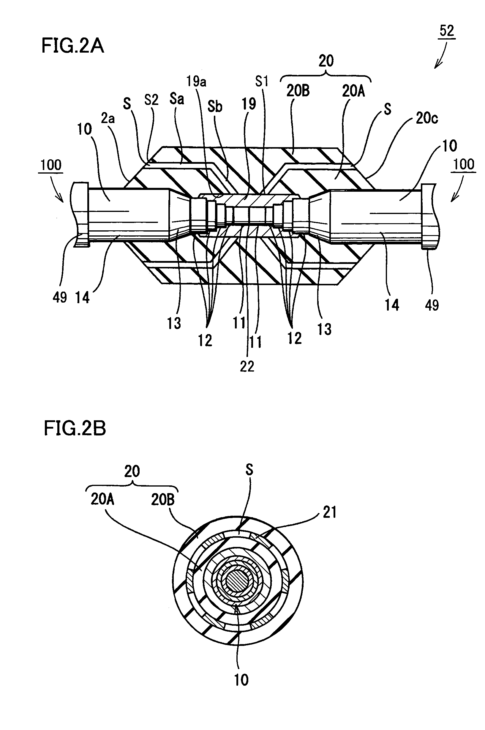
[0054]With reference to FIG. 2A, the present embodiment provides a superconducting cable joint structure 52. More specifically, two opposite cable cores 10 have their respective formers 11 and superconducting layers 12 each exposed stepwise so that they can be connected to conductor connection sleeve 19. Formers 11 abuts against each other and conductor connection sleeve 19, formed in a cylinder of metal (e.g., copper, aluminum or the like), is externally fitted and connected to establish a conductor connection 22.

[0055]Conductor connection sleeve 19 and superconducting layer 12 are electrically connected for example with solder, and conductor connection sleeve 19 and former 11 are compression-connected.

[0056]Conductor connection sleeve 19 is covered with first and second, coolant impregnated papers 20A and 20B wound therearound to serve as a joint insulation layer 20. As well as insulation layer 13, the first and second coolant impregnated papers 20A and 20B may als...

Example

SECOND EMBODIMENT

[0064]With reference to FIG. 3, the present embodiment differs from the first embodiment in that while the present embodiment provides a superconducting cable joint structure 53 including a joint insulation layer 20′ having a coolant path S′ extending along cable core 10, as seen longitudinally, and communicating at a portion adjacent to conductor connection sleeve 19.

[0065]Coolant path S′ has a horizontal portion Sa′ communicating an end Sf′ to coolant layer R, an inclined portion Sb′ communicating with horizontal portion Sa′ and having an end adjacent to conductor connection sleeve 19 at radially outer surface 19a, a horizontal portion Sd′ communicating an end Sg′ to coolant layer R, an inclined portion Se′ communicating with horizontal portion Sd′ and having an end adjacent to sleeve 19 at surface 19a, and a communication portion Sc′ allowing opposite inclined portions Sb′ and Se′ to have their respective ends communicating with each other.

[0066]More specifically...

Example

THIRD EMBODIMENT

[0069]In the present embodiment will be described a structure jointing together a terminal of a superconducting cable and a resin unit employed to secure a normal conducting cable.

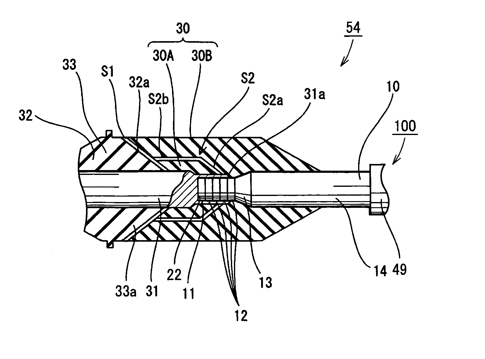
[0070]With reference to FIG. 4, the present embodiment differs from the first embodiment in that the present embodiment provides a superconducting cable joint structure 54 connecting the superconducting cable 100 cable core 10 to a conductor 31 of a resin unit 33 employed to secure a normal conducting cable to an external member.

[0071]In resin unit 33 conductor 31 formed of aluminum or copper is surrounded by a securing portion of insulator 32 formed of epoxy resin in the form of a rhomboid as seen in cross section. Securing portion of insulator 32 has an end with conductor 31 protruding and thus exposed, and having an end, connection portion 31a, which is externally fitted on and thus connected to superconducting layer 12 of cable core 10.

[0072]An outer surface of connection portion 31a, w...


PUM

PropertyMeasurementUnit
Temperatureaaaaaaaaaa
Circumferenceaaaaaaaaaa
Superconductivityaaaaaaaaaa

Abstract

A superconducting cable joint structure is a structure used to joint together superconducting cables used at cryogenic temperature or to joint together a terminal of the superconducting cable and a normal conducting cable, and it includes a joint insulation layer arranged radially outer than a portion connecting the superconducting cables' respective conductors together or the superconducting cable's conductor and the normal conducting cable's conductor together, and at least one coolant path provided at the joint insulation layer to cool the portion connecting the conductors together. The cable cores can have their connection prevented from generating heat to have an increased temperature.

Description

BACKGROUND OF THE INVENTION[0001]1. Field of the Invention[0002]The present invention relates generally to superconducting cable joint structures and more specifically to effectively preventing a conductor connection from overheating in jointing and thus connecting an end of a core of a superconducting cable to a counterpart conductor.[0003]2. Description of the Background Art[0004]Currently, cities and the like have a tendency to consume increasing amounts of power, and accordingly require larger underground power transmission capacities. Accordingly, a superconducting cable allowing as large a current density as approximately 100 times that of a conventional cable is being developed. This superconducting cable is, as disclosed for example in Japanese Patent Laying-Open No. 2002-140943, structured such that a plurality of cable cores having a superconductor pass through an external casing's internal space having liquid nitrogen or the like flowing therethrough to serve as a coolant...

Claims


Application Information

Patent Timeline
IPC IPC(8): H01B12/00H01B12/14H01B12/16H01B13/00H01R4/68
CPCH01R4/68H02G15/34Y10T29/49014Y02E40/648Y02E40/60
Inventor ASHIBE, YUUICHITAKAHASHI, YOSHIHISAHONJO, SHOICHIETOH, KEISUKE
Owner SUMITOMO ELECTRIC IND LTD
Why Eureka
Try Eureka