Multiple pressure mode operation for hydraulic hybrid vehicle powertrain

a hybrid vehicle and multi-pressure technology, applied in the direction of gas pressure propulsion mounting, propulsion parts, transportation and packaging, etc., can solve the problems of high system pressure, peak engine power, and often peak engine power, and achieve low system pressure, high efficiency, and quick transition

Active Publication Date: 2006-09-05
FORD GLOBAL TECH LLC
View PDF10 Cites 34 Cited by
  • Summary
  • Abstract
  • Description
  • Claims
  • Application Information

AI Technical Summary

Benefits of technology

[0009]Multiple accumulators, at different pressure states, can be connected to the system through valves, so that a quick transition from a low to a high pressure state can be made. Vehicle torque capability is then decoupled from stored energy, allowing more ideal pressure scheduling and use of regenerative braking, without adverse performance effects. Engine power at peak pressure can be combined with power available from stored energy, through separate pump motors, to achieve instantaneous power greater than the total engine power.

Problems solved by technology

In such a system, peak system drive torque, and often peak engine power, require a high system pressure.

Method used


Image

  • Multiple pressure mode operation for hydraulic hybrid vehicle powertrain
  • Multiple pressure mode operation for hydraulic hybrid vehicle powertrain
  • Multiple pressure mode operation for hydraulic hybrid vehicle powertrain

Examples


Embodiment Construction

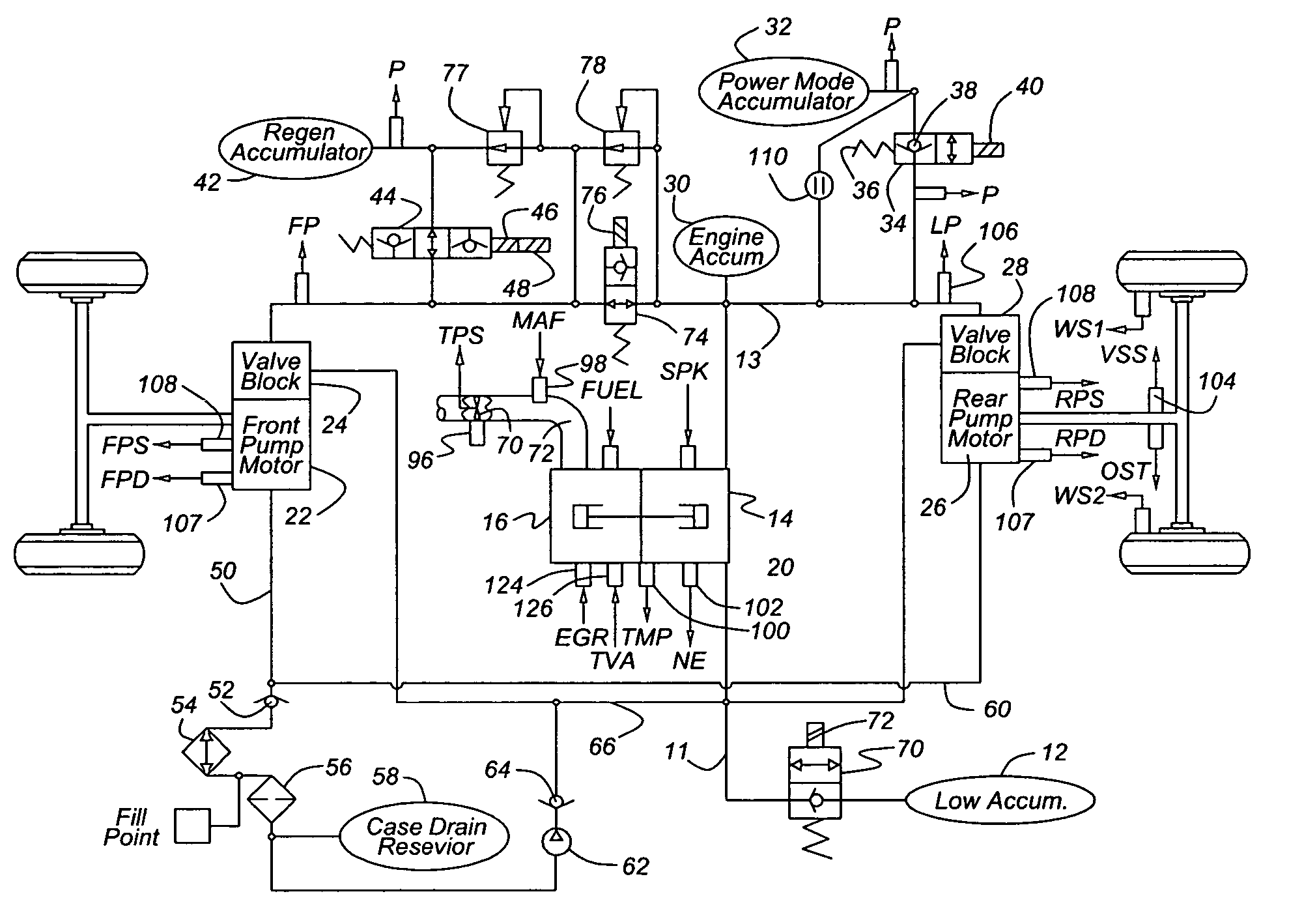
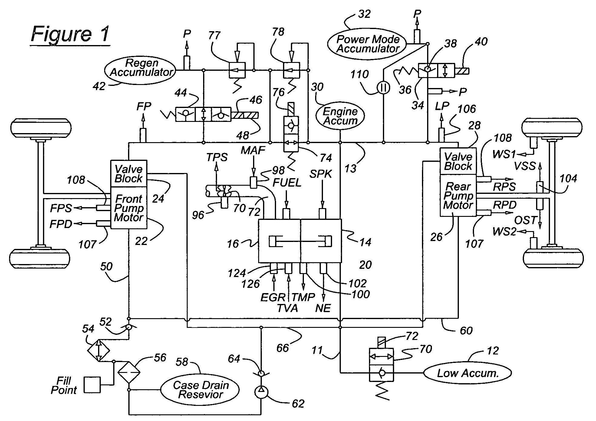
[0015]Referring now to the system illustrated in FIG. 1, an engine-pump 10 assembly is supplied with hydraulic fluid from a low pressure line 11, which is hydraulically connected to a low pressure accumulator 12. A main hydraulic rail 13, which contains fluid pressurized at line pressure, is connected to the outlet of the pump 14. Preferably pump 14 is a variable displacement pump. Engine 16 is preferably an internal combustion engine, such as a gasoline or diesel engine having a crankshaft, or a free piston engine having either spark ignition or compression ignition. Engine 16 drives the pump 14 and produces output torque or output hydraulic flow in response to control of one or more engine operating parameters including engine airflow, the engine throttle position, engine ignition timing, and engine air-fuel ratio.

[0016]A check valve may be used to close a connection between line 11 and the pump inlet when inlet pressure exceeds pressure in line 11. A check valve may be used to cl...


PUM


Abstract

A system for a hydraulically driven vehicle includes a pump producing fluid flow at an outlet, pump-motors having variable flow rates for driving the wheels, a hydraulic rail having a pressure and connecting the pump and the pump-motors, sensors producing signals representing rail pressure, pump-motor speed, pump-motor displacement, and a controller for determining a target hydraulic system parameter, determining, based at least in part on the flow rate of the pump-motor, rail pressure, and a flow rate produced by the engine-pump, a flow rate produced by the engine-pump that is required to produce the target system parameter, and adjusting an engine operating parameter of a cylinder-pump bank such that the demanded magnitude of the system parameter is produced.

Description

BACKGROUND OF THE INVENTION[0001]The invention relates to a hydraulic hybrid powertrain for vehicles, particularly to a powertrain having an engine-pump for pressurizing a hydraulic system, an accumulator for energy storage, and pump-motors for driving the wheels.[0002]In a hydraulic hybrid powertrain having a prime mover, such as an engine-pump that produces hydraulic flow at system pressure, and one or more pump-motors driving the wheels, it is desirable to operate at low system pressure to maximize the pump-motor efficiency during most operating conditions. There is, however, a mismatch in operating efficiency of the engine-pump and the efficiency of the pump-motors. The engine-pump has its highest efficiency at high system pressures. The pump-motors have their highest efficiency at lower system pressures.[0003]It is desirable to operate at a high system pressure at times of peak demand, to achieve the required power with a smaller pump-motor. Also, system pressure is directly co...

Claims


Application Information

Patent Timeline
Patent Type & Authority Patents(United States)
IPC IPC(8): B60K6/12B60K17/00B60W10/06B60W10/10B60W20/00
CPCB60K6/12B60W10/06B60W10/103Y02T10/6208B60W20/00Y02T10/62B60W10/30
Inventor ROETHLER, BOBKEPNER, RONLIPPERT, ROBERT
Owner FORD GLOBAL TECH LLC
Why Eureka
Try Eureka