
Steam turbine rotor, steam turbine and method for actively cooling a steam turbine rotor and use of active cooling

a technology of active cooling and steam turbine, which is applied in the direction of machines/engines, stators, liquid fuel engines, etc., can solve the problems of high disadvantage of rotor strength, inability to realize open cooling systems, and inability to apply cooling measures, etc., to achieve large-scale feasibility, high efficiency, and high steam parameters

Inactive Publication Date: 2006-09-05
SIEMENS AG
View PDF18 Cites 31 Cited by
  • Summary
  • Abstract
  • Description
  • Claims
  • Application Information

AI Technical Summary

Benefits of technology

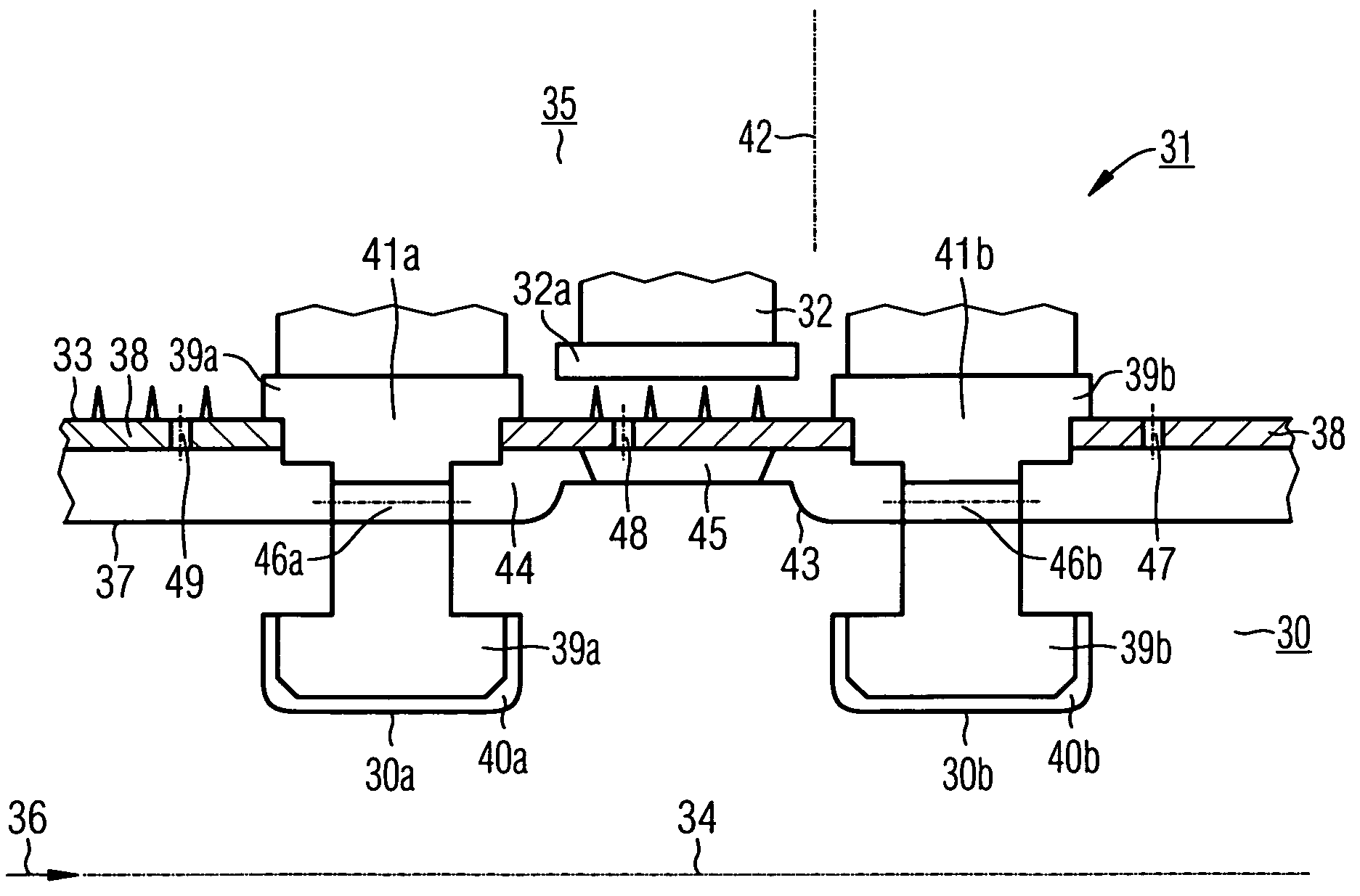
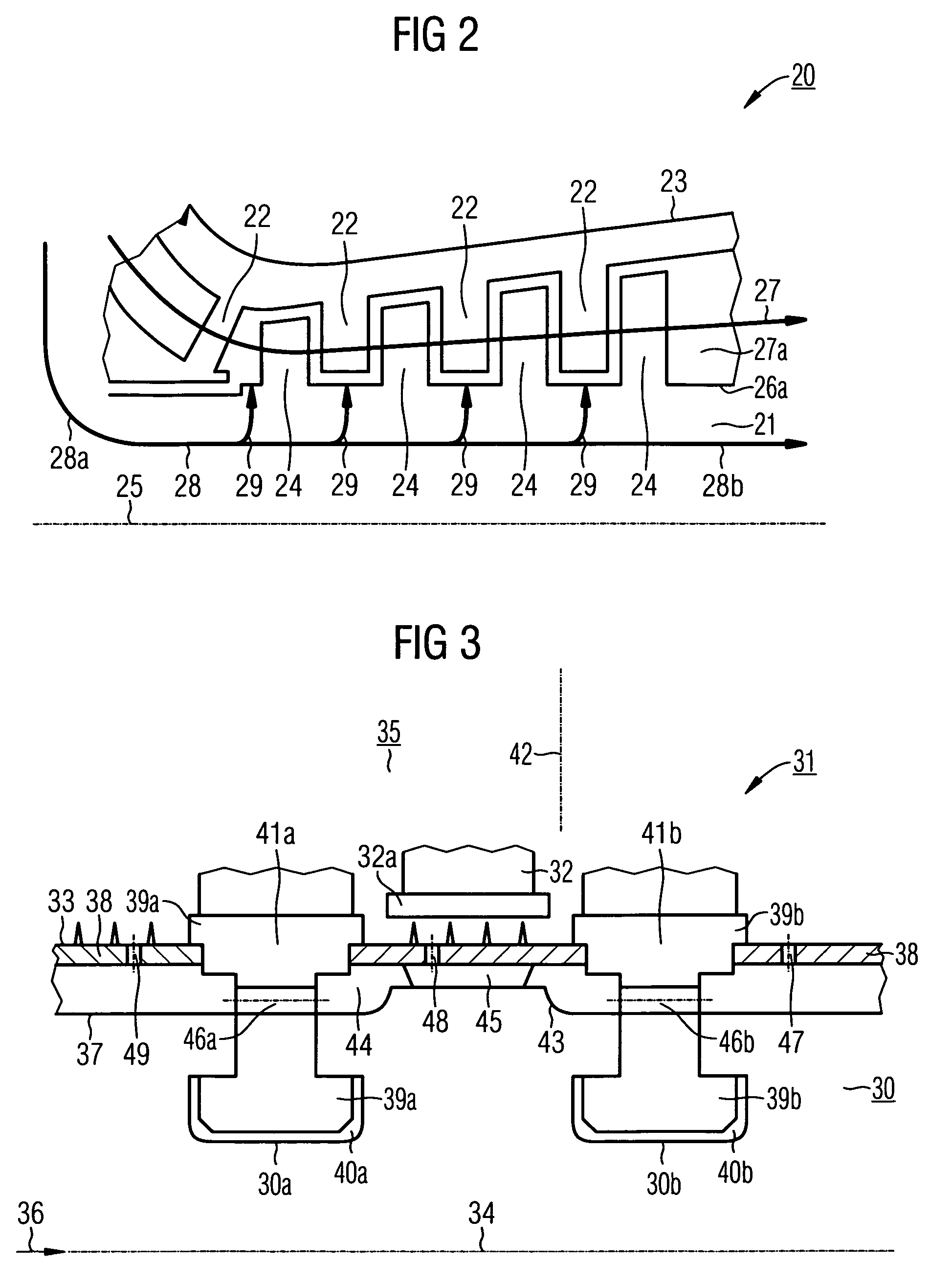
[0017]This has the significant advantage not only that the cooling of a steam turbine rotor takes place continuously over at least one, advantageously a plurality of, blade stages, i.e. at least between a first region arranged in front of the first location and a second region arranged behind the first location, but also that the dissipation of heat takes place in the immediate vicinity of where the heat is supplied, specifically in the vicinity of its surface. In this way, the cooling used in standard steam turbines is improved, meaning that they could be produced at lower materials costs. Furthermore the proposed cooling concept makes it possible to design new steam turbine concepts for higher entry parameters, in particular even for the highest steam parameters, as exist, for example, at temperatures of over 500° C. Examples of this are to be found in the above-referenced article “Neue Dampfturbinenkonzepte für höhere Eintritts-parameter und längere Endschaufeln” by H. G. Neft and G. Franconville. Examples for the steam parameters of the steam as a working medium are, for example, 250 bar and 545° C. or 300 bar and 600° C.
[0039]The preferred embodiment of the invention is described in connection with a cooling system which provides a pressure-matched mass flow of cooling steam which is able to cool the rotating components, i.e. the rotor and the rotor blades in a targeted manner. Consequently, the preferred embodiment proposed here can make a significant contribution to inexpensive, large-scale feasibility of higher steam parameters and higher efficiencies. Furthermore, an embodiment of the invention as described here, or a slightly different, modified embodiment, can also be implemented in order to allow the use of less expensive rotor and blade materials for current steam parameters.

Problems solved by technology

Therefore, an open cooling system cannot be realized without a cooling medium being supplied from the outside of the part-turbine.
It has consequently proven impossible for cooling measures which are known from gas turbines to be transferred to steam turbines in the form which is known for gas turbines and is only suitable for gas turbines.
Since the central cavity and the branch channels are arranged at the location where the component is subject to the highest levels of loading, this is highly disadvantageous for the rotor strength.
It has the further drawback that a temperature difference across the rotor wall has to remain limited, since otherwise the rotor would be excessively thermally deformed in the event of an excessive temperature difference.
For these reasons, a concept of this nature has not yet achieved widespread use.
Hitherto, it has not been possible to achieve sufficient dissipation of heat in the immediate vicinity of where the heat is supplied.
In the process, the steam is cooled by approximately 10 K. However, this method can only achieve a very limited cooling action on the rotor.
U.S. Pat. No. 6,102,654 realizes active cooling of a steam turbine rotor to only a very restricted extent, and moreover the cooling is limited to the inflow region of the hot working medium.
The cooling effect on the rotor which can be achieved as a result is limited, since it is restricted to the inflow region of the main flow.
Furthermore, the bore disadvantageously increases the rotor stresses significantly compared to the configuration without a bore.
Moreover, the cooling is restricted to the main flow region of the working medium and is still in need of improvement.
When higher steam parameters are applied to standard steam turbines, an increased thermal load may result over the entire turbine, and this load could only be alleviated to an insufficient degree by standard cooling of the rotor as described above.
This gives rise to the problem that when turbine materials which have hitherto been customary are employed, the increasing load on the rotor resulting from increased steam parameters may lead to a disadvantageous thermal load on the rotor and to an unacceptable increase in the temperature of the rotor.

Method used


Image

  • Steam turbine rotor, steam turbine and method for actively cooling a steam turbine rotor and use of active cooling
  • Steam turbine rotor, steam turbine and method for actively cooling a steam turbine rotor and use of active cooling
  • Steam turbine rotor, steam turbine and method for actively cooling a steam turbine rotor and use of active cooling

Examples


Embodiment Construction

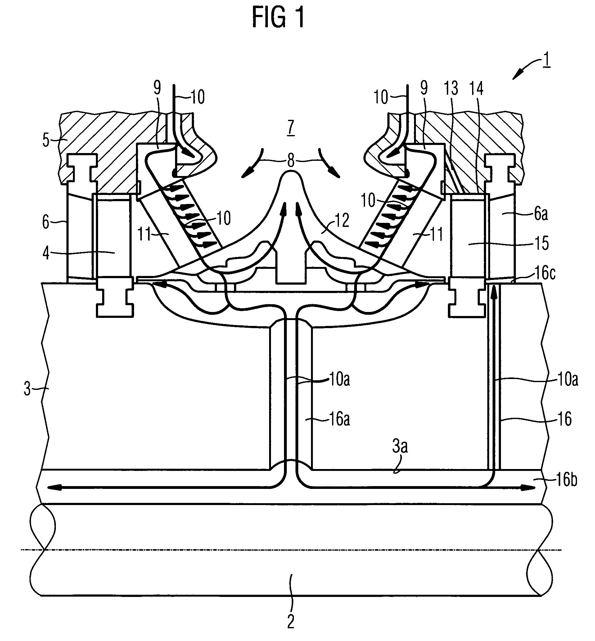
[0052]Known steam turbine rotors are fundamentally manufactured as solid, single-piece rotors, without any active cooling systems whatsoever. However, as illustrated in FIG. 1, the prior art in accordance with U.S. Pat. No. 6,102,654 has described a steam turbine 1 which has a cooling system which is restricted to cooling in the inflow region. This turbine has a rotor 3 arranged rotatably on an axle 2, with a number of rotor blades 4 arranged on its tubular shaft. These rotor blades are arranged in a stationary casing 5 with a set of guide vanes 6. The rotor 3 is driven by the working medium 8, which flows in in the inflow region 7, via the rotor blades 4. In addition to the working medium 8, a cooling medium 10 flows to the working medium 8 via a separate inlet region 9. The cooling medium 10 performs a cooling action only on a first ring 11 of the stationary guide vanes and a shielding plate 12 by flowing on to them. As a result, the thermal load on the rotor 3 and the first ring ...


PUM


Abstract

The proposed steam turbine rotor extends along an axial extent and includes: an outer side which adjoins an outer space which is intended to receive a main flow of a fluid working medium, a first location along the outer side, at which a first blade is held, a second location along the outer side, at which a second blade is held, the second location being arranged behind the first location along the axial extent. To ensure sufficient cooling, there is at least one integrated passage, which extends continuously at least between a first region arranged in front of the first location and a second region arranged behind the second location The invention proposes a method and a use in which a fluid cooling medium is guided in a corresponding way.

Description

CROSS REFERENCE TO RELATED APPLICATIONS[0001]This application claims priority to the European application No. 03002472.3 EP, filed Feb. 5, 2003 under the European Patent Convention and which is incorporated by reference herein in its entirety.FIELD OF INVENTION[0002]The invention relates to a steam turbine rotor which extends along an axial extent and includes: an outer side, which adjoins an outer space which is intended to receive a main flow of a fluid working medium and a first location along the outer side, at which a first row of blades is held. The invention also relates to a steam turbine. Furthermore, the invention relates to a method for actively cooling a steam turbine rotor of said type.BACKGROUND OF INVENTION[0003]When hot steam is applied to a steam turbine as working medium, targeted cooling of highly loaded components is desirable in order to increase the steam temperatures which can be reached. Where possible, this targeted cooling encompasses shielding and dissipat...

Claims


Application Information

Patent Timeline
Patent Type & Authority Patents(United States)
IPC IPC(8): F01D5/14F01D5/08F01D5/18F01D9/02F01D25/12
CPCF01D5/084F05D2220/31F05D2260/202F05D2260/85F05D2260/2322F05D2230/90
Inventor HAJE, DETLEFROTTGER, DIETMAR
Owner SIEMENS AG
Learn More