Magnetic recording and reproducing apparatus and magnetic recording medium

a recording and reproducing apparatus technology, applied in the direction of maintaining head carrier alignment, track following on tapes, instruments, etc., can solve the problems of narrowed track resolution, inability to achieve the level of accuracy, and inability to empirically measure the servo bandwidth above approximately 18 of the sampling period, etc., to achieve remarkable enhancement in recording density. the effect of magnetic recording and reproducing

Inactive Publication Date: 2006-09-12
KK TOSHIBA
View PDF27 Cites 34 Cited by
  • Summary
  • Abstract
  • Description
  • Claims
  • Application Information

AI Technical Summary

Benefits of technology

[0043]As a result, those and other embodiments can realize magnetic recording and reproduction remarkably enhanced in recording density.

Problems solved by technology

Problems involved in this movement are thermal agitation of media, field detecting sensitivity of heads, and positioning accuracy of heads.
As for the head-positioning servo technique, however, no hopeful measures coping with narrowed tracks have been envisioned heretofore.
This level of accuracy is extremely difficult to achieve.
Thus the most important issue to be contemplated for enhancing the performance of the servo system is the latter issue, namely, the sampling period.
In servo control, however, the sampling period of the servo information is a constraint that restricts the servo bandwidth, and the servo bandwidth cannot be higher than approximately ⅛ of the sampling period empirically.
The later method, however, may invite an increase of “swinging rotation” with the increase of the rotational speed.
Actually, the rate of occupation by the servo area surface is determined at the trade-off between the ratio of the servo area surface and the servo performance, but it is undesirable that the servo area surface increases to and beyond 10%.
In this case, the ratio of the disk surface occupied by the header portion is too large, and the data region decreases.
This problem is serious in case of the 1-Tbpsi class surface recording density, and there is the demand for a method capable of increasing the sampling period without increasing sectors.
Any of these techniques, however, invites deterioration of S / N of reproduced signals when it is applied to HDD.
Decreasing the leak magnetic field from the disk recording magnetic field to the reproducing head or increasing the noise magnetic field from any adjacent track, etc. makes it impossible to keep sufficient S / N of reproduced signals.
In other words, it results in locating the electrode between the pair of reproducing elements in the central portion where the magnetic field profile of the signal recorded on the track is highest, and the read loss is large.
Its reason lies in that the error information contained in the detection signal itself is very small in comparison with the signal information and S / N of the extracted error signal is bad accordingly.
Thus it is difficult to increase the servo rigidity.
If there are errors, they may decrease S / N of the reproduced signal.
As explained above, for realizing superdense HDD, conventional techniques require continuous servo capable of simultaneously detecting error signals and reproduced signals with sufficient sensitivity over a sufficient bandwidth, but deterioration of S / N ratio of the reproducing head and other problems make it difficult to realize superdense HDD.

Method used


Image

  • Magnetic recording and reproducing apparatus and magnetic recording medium
  • Magnetic recording and reproducing apparatus and magnetic recording medium
  • Magnetic recording and reproducing apparatus and magnetic recording medium

Examples


first embodiment

[0062](First Embodiment)

[0063]As the first embodiment of the invention, explanation is first made on a magnetic recording and reproducing apparatus and a 1 Tbpsi class HDD system using a magnetic recording medium suitable for the magnetic recording and reproducing apparatus.

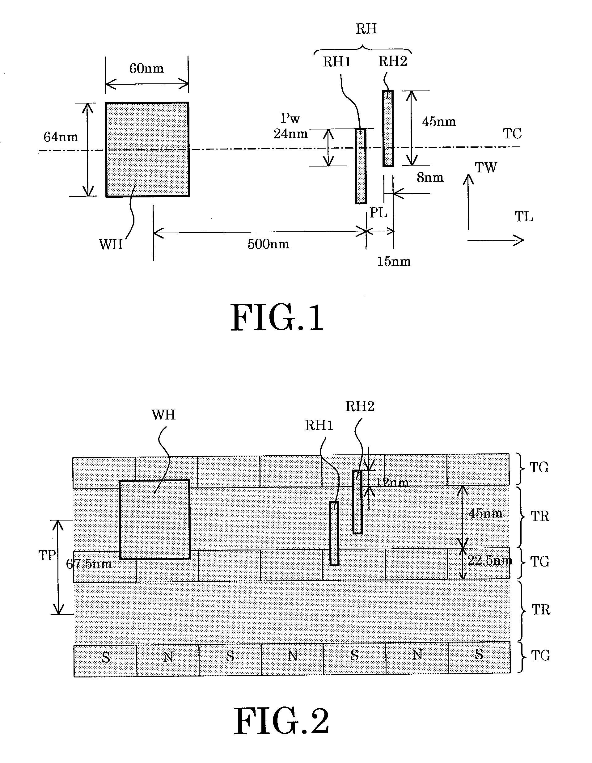
[0064]FIG. 1 is a conceptual diagram exemplifying a basic plane configuration of a magnetic head used in a magnetic recording and reproducing apparatus according to the first embodiment of the invention.

[0065]This magnetic head includes a write region WH for the recording head and a magnetic detection region RH for the reproducing head, which are aligned along the lengthwise direction of tracks of a recording medium, not shown. A magnetic shield, not shown is adequately provided between the write region WH and the magnetic detection region RH.

[0066]The magnetic detection region RH for the reproducing head includes two magnetic detection regions RH1, RH2 that are offset in both lengthwise and widthwise directions ...

second embodiment

[0107](Second Embodiment)

[0108]Next explained is the second embodiment of the invention by way of a specific example using the head configuration of the first embodiment and using a different recording medium with reference to FIGS. 7 and 8. The configuration shown here is a specific example using a recording medium in which the guard band TG is uniformly magnetized to the N pole. This facilitates the manufacture of the recording medium and simplifies the signal processing circuit, etc.

[0109]FIG. 7 shows a recording medium accessed by the head. In this specific example, the magnetic recording medium has a structure alternately arranging writing-available recording tracks TR and writing-prohibited guard bands TG. The recording tracks TR are made of a material available for recording by the record magnetic field applied from the write region WH. The guard bands TG are made of a material that disables writing by the signal magnetic field from the write region WH. However, the guard ban...

third embodiment

[0117](Third Embodiment)

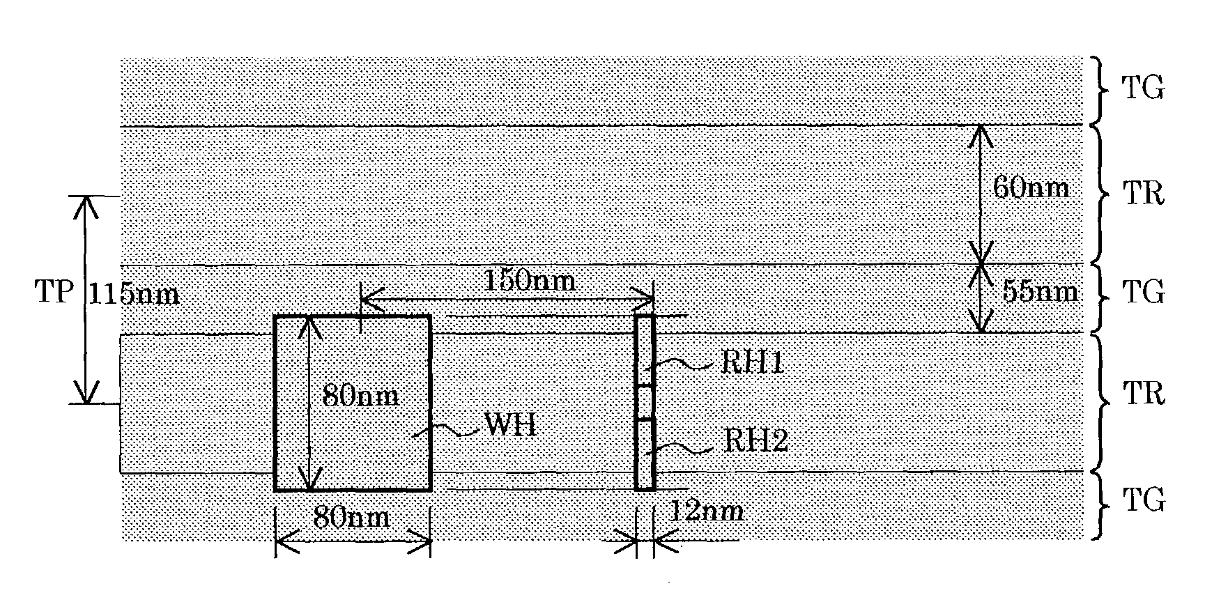
[0118]Next explained is a 400 Gbpsi-class HDD system combining a vertically magnetized patterned medium according to an embodiment of the invention with double reproducing heads disclosed in Japanese Patent Laid-Open Publication No. hei 06-215322, for example, with reference to FIGS. 10 through 13. The specific example shown here is a system in which the track pitch of the recording medium is 115 nm, and the minimum bit length is 14 nm. Its head accessing mechanism may be of a type using an arm configuration with the same length as the conventional one and varying in skew angle between inner circumferential portions and outer circumferential portions of the medium disk.

[0119]FIG. 10 is a conceptual diagram illustrating the head located on the magnetic recording medium in the third embodiment of the invention. The magnetic recording medium has a structure alternately arranging 55 nm wide guard bands TG and 60 nm wide recording tracks TR, and the guard bands TG...


PUM

PropertyMeasurementUnit
bit lengthaaaaaaaaaa
widthaaaaaaaaaa

Abstract

A magnetic recording and reproducing apparatus extracts a record signal from a sum signal (ADD) of signals detected via first and second magnetic detection regions (RH1, RH2) that are formed to be offset in the lengthwise (TL) and widthwise (TW) directions of a recording track having an overlapping part in the widthwise direction (TW), and extracts servo information from a sub signal (SUB).

Description

CROSS-REFERENCE TO RELATED APPLICATIONS[0001]This application is based upon and claims the benefit of priority from the prior Japanese Patent Application No. 2001-401967, filed on Dec. 28, 2001; the entire contents of which are incorporated herein by reference.BACKGROUND OF THE INVENTION[0002]This invention relates to a magnetic recording and reproducing apparatus and a magnetic recording medium. More particularly, the invention relates to a magnetic recording and reproducing apparatus for recording and reproducing signals as magnetic information on and from a disk-shaped magnetic recording medium, and a magnetic recording medium suitable for use in the apparatus.[0003]Recently, hard disks are enhanced in density at the rate of nearly twice a year. Problems involved in this movement are thermal agitation of media, field detecting sensitivity of heads, and positioning accuracy of heads. Among these problems, thermal turbulence of media is considered solvable to a certain extent by re...

Claims


Application Information

Patent Timeline
Patent Type & Authority Patents(United States)
IPC IPC(8): G11B5/596G11B5/65G11B5/265G11B5/592G11B21/10
CPCG11B5/59633G11B5/5926G11B5/012
Inventor ASAKURA, MAKOTO
Owner KK TOSHIBA
Why Eureka
Try Eureka