Random array of microspheres

a random array and microsphere technology, applied in the field of biological microarray technology, can solve the problems of inability to accurately predict the exact the cost of the method, and the inability to accurately predict the size of the array, so as to facilitate the access of analyte, facilitate the preparation, and reduce the cost

Inactive Publication Date: 2006-09-19
CARESTREAM HEALTH INC
View PDF9 Cites 12 Cited by
  • Summary
  • Abstract
  • Description
  • Claims
  • Application Information

AI Technical Summary

Benefits of technology

[0021]The present invention provides a microarray that is less costly and easier to prepare than those previously disclosed because the substrate does not have to be modified; nevertheless the microspheres remain immobilized on the substrate.
[0022]Further, the present invention provides a microarray wherein, in contrast to D82300, the bead surfaces are exposed but without employing the additional process step (enzyme digestion) disclosed in D83451. Exposed bead surfaces facilitate easier access of the analyte to probes attached to the surfaces of the beads. By “analyte” is meant molecules with functionalities capable of interacting chemically or physically with specific moieties on the bead surface, herein called “probes”. In the present invention, the analyte is primarily nucleic acids or proteins.

Problems solved by technology

This method is expensive.
An ink jet approach is being used by others (e.g., U.S. Pat. Nos. 6,079,283; 6,083,762; and 6,094,966) to fabricate spatially addressable arrays, but this technique also suffers from high manufacturing cost in addition to the relatively large spot size of 40 to 100 μm.
Because the number of bioactive probes to be placed on a single chip usually runs anywhere from 1000 to 100000 probes, the spatial addressing method is intrinsically expensive regardless how the chip is manufactured.
The problem is that during such machine coating and rapid gelation, the gelling agent tends to cover the surface of the microspheres, thereby preventing the analyte (such as DNA) from penetrating through the gel overcoat and hybridizing with probes on the surface of the microspheres.
However, there is a disadvantage in that an additional process (enzyme digestion) is required and this involves additional time and cost.

Method used


Image

  • Random array of microspheres
  • Random array of microspheres
  • Random array of microspheres

Examples


example 1 (

Control)

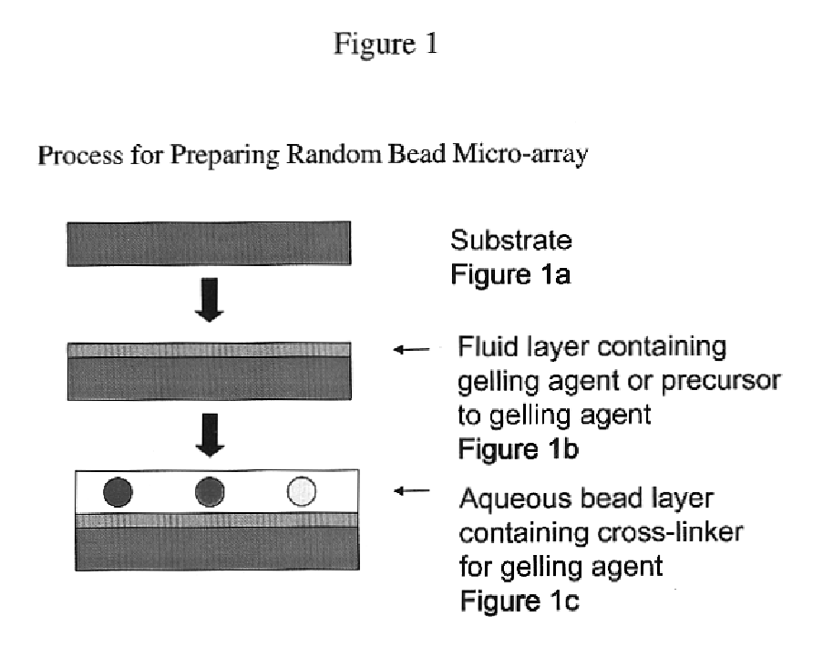
[0039]This and the following example illustrate the method of coating or fabricating a well-dispersed random array of microspheres wherein the surfaces of the micro-spheres are exposed above the surface of the receiving layer in which they are partially submerged.

[0040]Ten grams of a 4% aqueous suspension of carboxylated polystyrene beads prepared by emulsion polymerization and having a mean size of 10 microns was combined with 0.1 grams of poly(vinyl alcohol) (Gohsenol NK-05 from Nippon Gohsei; 71-75% hydrolyzed).

[0041]A suspension of magenta colored beads was prepared by first dissolving 0.01 grams of Dye 1 (MM2500EVV) in 0.05 grams of toluene and 4.95 grams of acetone. The above suspension of polystyrene beads was then added slowly (drop-wise) to this solution of the dye while stirring to prepare a suspension of colored beads. The suspension of colored beads was then filtered using a porous cotton filter, poured into a dialysis bag (12,000 to 14,000 molecular weight cut-o...

example 2 (

Invention)

[0048]This Example is the same as example 1, but characterized by the absence of gelling agent in the dispersion of microspheres.

[0049]Suspensions of magenta, cyan and yellow colored beads (containing Dye 1, Dye 2 and Dye 3 respectively) were prepared in a manner similar to that described under Example 1. In addition a suspension of purple colored beads containing Dye 4 was also prepared. The concentration of colored beads in these suspensions was close to 1% in all cases.

Formulations for coating were prepared as follows.

[0050]Receiving Layer: This was prepared in the same manner as described under Example 1.[0051]Dispersion of Microspheres: An aqueous composition with colored beads and no gelling agent was prepared by combining 1.5 grams of the suspension of magenta colored beads, 1.5 grams of the suspension of cyan colored beads and 1.5 grams of the suspension of yellow colored beads, 8 grams of the suspension of purple colored beads and 1.8 grams of clear non-colored be...

example 3

[0054]This example illustrates the effect of cross-linking the gelatin (gelling agent) in the sub-layer prior to coating the main layer.

[0055]Magenta, Cyan and Purple colored beads were prepared in a manner analogous to that described in Examples 1 and 2. The final concentrations of beads in these suspensions were 0.84%, 0.93% and 1.21% respectively.

Formulations for coating were prepared in the following manner.

[0056]Receiving Layer 1 (control): This was prepared by combining 87 grams of acid processed ossein gelatin (gelling agent), 50 grams of cross-linking agent for the gelatin (1.8% solution of bis(vinylsulfonyl)methane in water), 20 grams of coating aid (10.8% solution of Olin 10G in water) and 343 grams of distilled water.[0057]Receiving Layer 2 (invention): The composition was the same as that for receiving layer 1 except that it did not contain a cross-linking agent.[0058]Dispersion of Microspheres: This was prepared by combining 10.9 grams of the suspension of magenta color...


PUM

PropertyMeasurementUnit
mean diameteraaaaaaaaaa
diameteraaaaaaaaaa

Abstract

A method of making a microarray comprising the steps of:providing a support;coating on the support a receiving layer to receive microspheres, the receiving layer being capable of undergoing sol / gel transition;coating on the receiving layer a dispersion of microspheres in a carrier fluid, wherein the carrier fluid contains at least one crosslinking agent and is capable of solvating the receiving layer;allowing the microspheres to partially submerge into the receiving layer;creating conditions to induce sol / gel transition in the receiving layer, thus immobilizing the microspheres;evaporating off the carrier fluid; andallowing crosslinking reaction between the receiving layer and the crosslinker in the carrier fluid.

Description

FIELD OF THE INVENTION[0001]The present invention concerns biological microarray technology in general. In particular, it concerns a microarray coated on a substrate that contained no sites designated prior to coating to attract the microspheres.BACKGROUND OF THE INVENTION[0002]Ever since it was invented in the early 1990s (Science, 251, 767-773, 1991), high-density arrays formed by spatially addressable synthesis of bioactive probes on a 2-dimensional solid support has greatly enhanced and simplified the process of biological research and development. The key to current microarray technology is deposition of a bioactive agent at a single spot on a microchip in a “spatially addressable” manner.[0003]Current technologies have used various approaches to fabricate microarrays. For example, U.S. Pat. Nos. 5,412,087, and 5,489,678 demonstrate the use of a photolithographic process for making peptide and DNA microarrays. The patent teaches the use of photolabile protecting groups to prepa...

Claims


Application Information

Patent Timeline
Patent Type & Authority Patents(United States)
IPC IPC(8): B05D1/36B05D5/00B01J19/00C40B40/06C40B40/10C40B70/00
CPCB01J19/0046B01J2219/00466B01J2219/005B01J2219/00545B01J2219/00554B01J2219/00596C40B70/00B01J2219/00648B01J2219/00722B01J2219/00725C40B40/06C40B40/10B01J2219/00639
Inventor CHARI, KRISHNANQIAO, TIECHENG A.HANUMANTHU, RAMASUBRAMANIAM
Owner CARESTREAM HEALTH INC
Why Eureka
Try Eureka