
Tailored collector voltage to minimize variation in AM to PM distortion in a power amplifier

Active Publication Date: 2006-09-19
QORVO US INC
View PDF69 Cites 111 Cited by
  • Summary
  • Abstract
  • Description
  • Claims
  • Application Information

AI Technical Summary

Benefits of technology

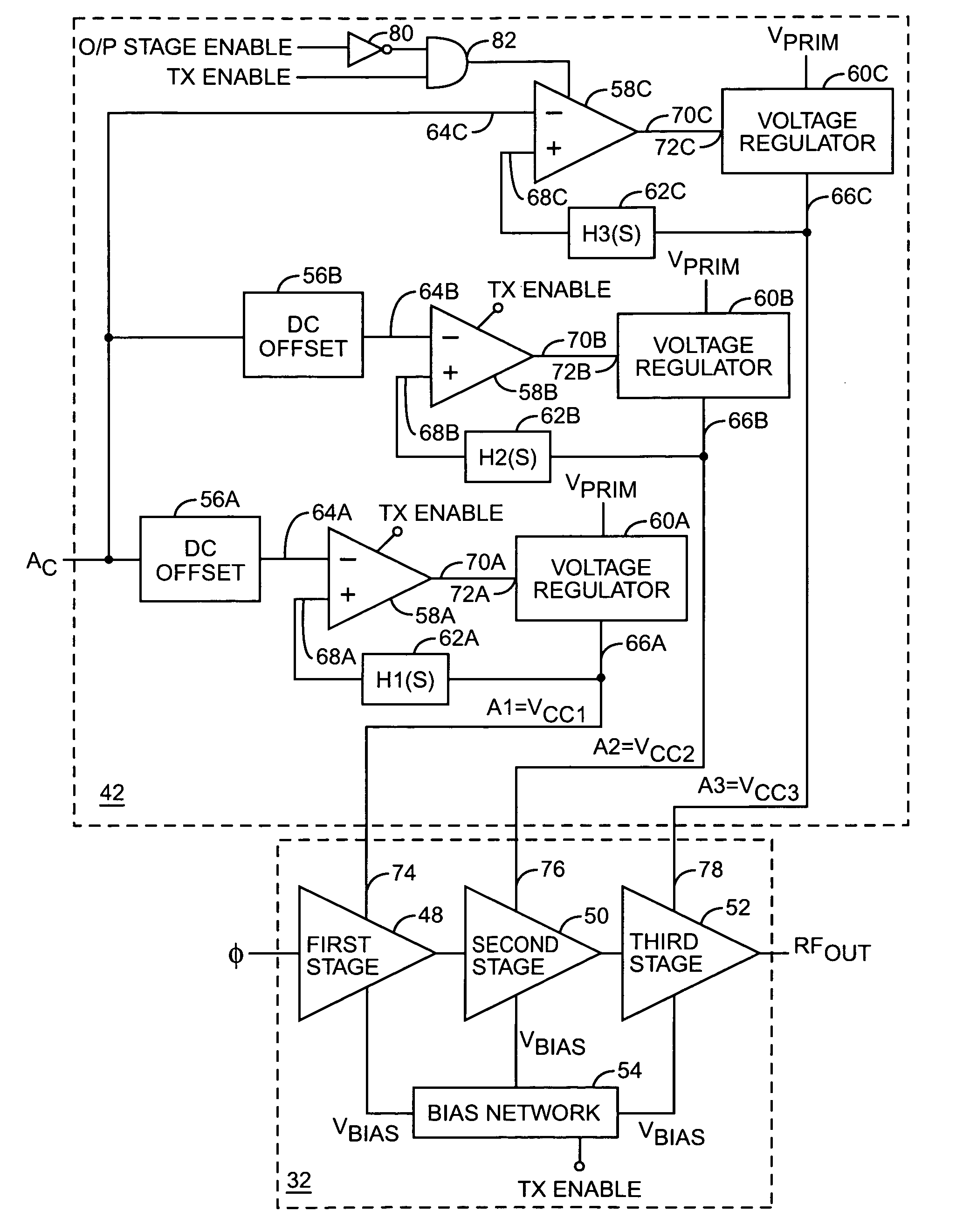
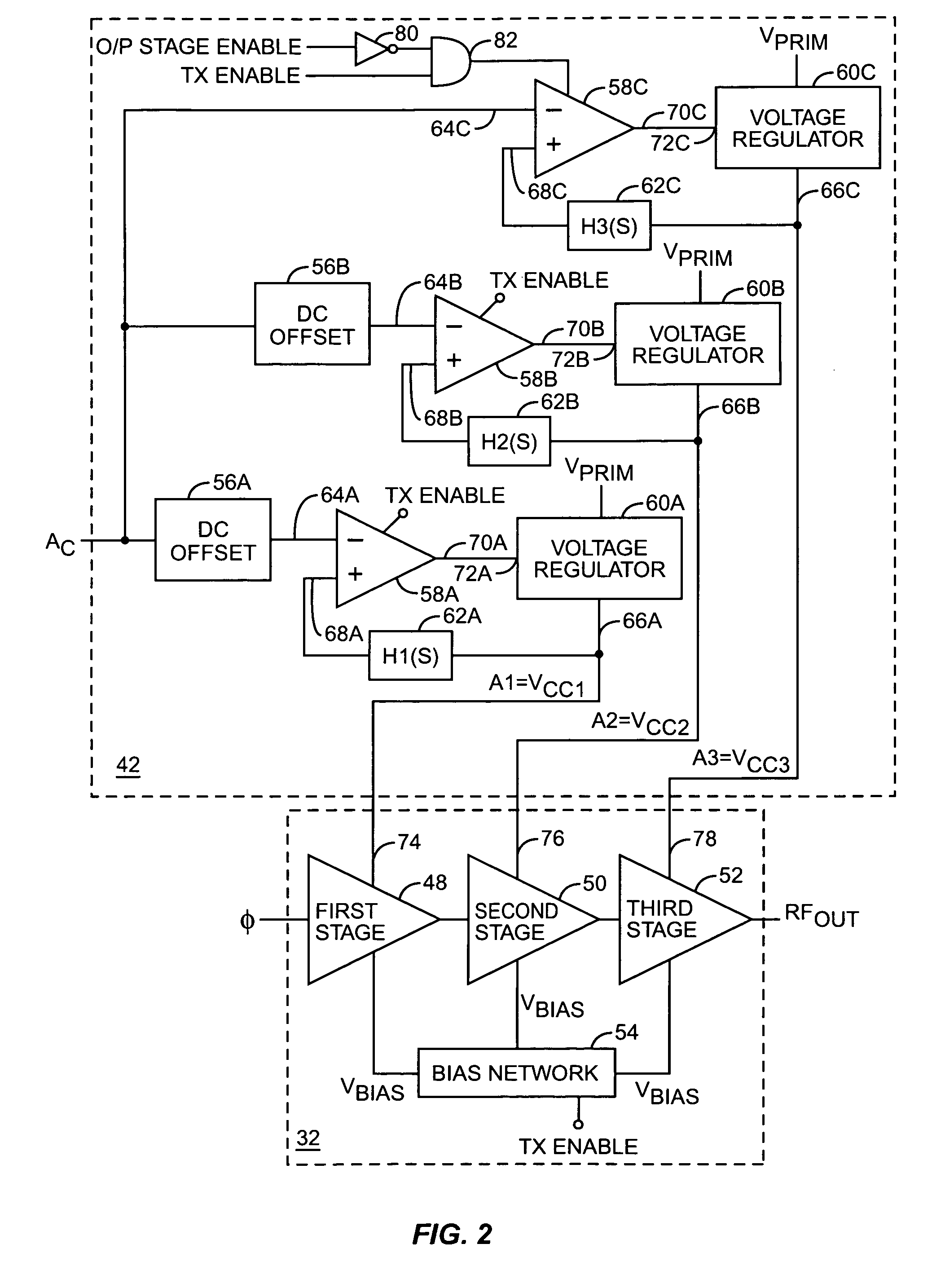
[0005]The present invention provides a system for substantially reducing variation in AM to PM distortion of a power amplifier caused by variations in RF drive power and temperature. In general, the system includes power control circuitry and power amplifier circuitry. The power amplifier circuitry includes an input amplifier stage and at least one additional amplifier stage coupled in series with the input amplifier stage. The power control circuitry provides a first supply voltage to the input amplifier stage based on a control signal such that the first supply voltage has a predetermined DC offset with respect to the control signal. The predetermined DC offset is provided such that the first supply voltage having the predetermined offset substantially reduces variations in the AM to PM distortion of the power amplifier due to variations in radio frequency (RF) drive power at the input of the power amplifier circuitry. The predetermined DC offset may also be provided in order to substantially reduce variations in the AM to PM distortion due to variations in temperature in addition to variations in the AM to PM distortion due to variations in RF drive power.
[0008]In one embodiment, the at least one additional amplifier stage includes a second amplifier stage coupled in series with the input amplifier stage and an output amplifier stage coupled in series with the second amplifier stage. The power control circuitry provides the first supply voltage to the input amplifier stage and a second supply voltage to the second amplifier stage. Similarly to the first supply voltage, the power control circuitry may provide the second supply voltage based on the control signal such that the second supply voltage has a predetermined DC offset and gain with respect to the control signal. The predetermined DC offset and gain of each of the first and second supply voltages are selected such that the combined effect of the first and second supply voltages is to substantially reduce variations in the AM to PM distortion of the power amplifier due to variations in RF drive power. The DC offsets and gains of the first and second supply voltages may also be selected such that the combined effect of the first and second supply voltages is to substantially reduce variations in the AM to PM distortion of the power amplifier due to variations in temperature rather than or in addition to substantially reducing the variations in the AM to PM distortion of the power amplifier due to variations in RF drive power.

Problems solved by technology

Such a linear system lacks the efficiency of one that operates the power amplifier in saturation.
In a polar modulation system, the amplitude component of a polar signal controls the power amplifier and will cause unwanted phase components to be created in the output of the power amplifier due to the non-linearities of the power amplifier.
This is sometimes called amplitude modulation to phase modulation (AM to PM) distortion, and it degrades the spectral purity of the system and the Error Vector Magnitude.
Further, the AM to PM distortion of the power amplifier may vary depending on factors such as the radio frequency (RF) power at the input of the amplifier and temperature.

Method used


Image

  • Tailored collector voltage to minimize variation in AM to PM distortion in a power amplifier
  • Tailored collector voltage to minimize variation in AM to PM distortion in a power amplifier
  • Tailored collector voltage to minimize variation in AM to PM distortion in a power amplifier

Examples


Embodiment Construction

[0016]The embodiments set forth below represent the necessary information to enable those skilled in the art to practice the invention and illustrate the best mode of practicing the invention. Upon reading the following description in light of the accompanying drawing figures, those skilled in the art will understand the concepts of the invention and will recognize applications of these concepts not particularly addressed herein. It should be understood that these concepts and applications fall within the scope of the disclosure and the accompanying claims.

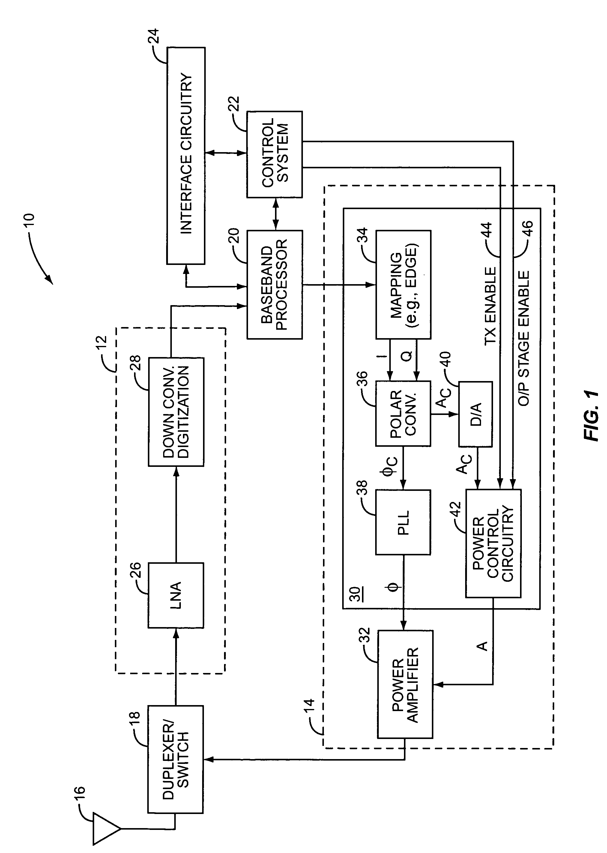
[0017]The present invention is preferably incorporated in a user element 10, such as a mobile telephone, personal digital assistant, wireless modem, wireless network interface, or the like, which implements polar modulation. The basic architecture of the user element 10 is represented in FIG. 1 and may include a receiver front end 12, a radio frequency transmitter section 14, an antenna 16, a duplexer or switch 18, a baseband proc...


PUM


Abstract

A system is provided for substantially reducing variation in AM to PM distortion of a power amplifier caused by variations in RF drive power and temperature. The system includes power control circuitry and power amplifier circuitry. The power amplifier circuitry includes an input amplifier stage and at least one additional amplifier stage coupled in series with the input amplifier stage. The power control circuitry provides a first supply voltage to the input amplifier stage based on a control signal such that the first supply voltage has a predetermined DC offset with respect to the control signal. The first supply voltage is provided such that the predetermined DC offset substantially reduces variations in the AM to PM distortion of the power amplifier due to variations in radio frequency (RF) drive power.

Description

FIELD OF THE INVENTION[0001]The present invention relates to power amplifiers and more particularly relates to controlling a power amplifier to reduce variation in AM to PM distortion.BACKGROUND OF THE INVENTION[0002]Transmitters form a significant portion of most communication circuits. As such, they assume a position of prominence in design concerns. With the proliferation of mobile terminals, transmitter design has progressed in leaps and bounds as designers try to minimize components and reduce size, power consumption, and the like. Likewise, modulation schemes are continuously updated to reflect new approaches to maximize information transfers within limited bandwidth constraints.[0003]One relatively recent change has been the advent of the Enhanced Data for GSM Evolution (EDGE) scheme in GSM systems. This system contains amplitude modulation components, and, as a result, the power amplifier must be linear and should not operate in saturation when classical modulation technique...

Claims


Application Information

Patent Timeline
IPC IPC(8): H03G5/16H03G9/00
CPCH03F1/0211H03F1/32H03G3/3042H03G3/004H03F2200/516H03F2200/408
Inventor EPPERSON, DARRELL G.BOSLEY, RYAN
Owner QORVO US INC
Learn More