Biosensor

a biosensor and sensor technology, applied in the field of biosensors, can solve the problems of difficult to analyze blood general constituents, unfavorable chromatographic sensors, and difficult to perform the measurement directly with whole blood, and achieve the effect of convenient portability and easy handling

Inactive Publication Date: 2006-09-26
PHC HLDG CORP
View PDF15 Cites 107 Cited by
  • Summary
  • Abstract
  • Description
  • Claims
  • Application Information

AI Technical Summary

Benefits of technology

[0040]According to the so-constituted biosensor, the whole biosensor is a dry support body, and thus it is easy to carry and there is no need for strict management of preservation environment and condition, resulting in a biosensor which is easy to deal with, has no preference with respect to the preservation condition, and can be stored for a long time.

Problems solved by technology

For example, a measurement of a kind or concentration of a metabolic product, a protein, lipid, an electrolyte, an enzyme, an antigen, an antibody and the like, which are constituents in blood, is performed, while it is hard to perform the measurement directly with whole blood when the above-described immunochromatographic sensor is employed.
However, the centrifugation takes labor and time, and thus this chromatographic sensor is unfavorable particularly when a small number of specimens are to be processed immediately or when the examination is to be performed out of doors, at bed side, in the scene of emergency medical care and the like, where facilities for the above operation are not prepared.
However, according to a biosensor typified by the conventional immunochromatographic sensor, it is difficult to analyze general constituents of blood.
Accordingly, not only a specific machine but also a pretreatment are required for the measurement, so that the examination takes a long time.
However, according to this method, efficiency of blood corpuscle separation is surely enhanced, while it takes quite a long time to almost completely separate the blood corpuscles and a large amount of blood is required to obtain the amount of specimen required for the examination.
However, this method requires operations of adding the applying water solution to previously obtained blood and filtrating the blood corpuscle components thereafter, whereby the operation becomes complicated, the measurement takes time, and it is impossible to deal with the examination in an emergency.
Although, in this method, the blood specimen can develop on the chromatographic specimen in a short time even without being somehow pretreated previously, a background value is increased and a S / N ratio is decreased due to influence of a blood pigment in the developing blood, whereby a sensitivity in a measurement employing a device is reduced, and the blood pigment prevents reading of a coloration degree, which results in extremely low accuracy for a quantitative measurement.

Method used


Image

  • Biosensor
  • Biosensor
  • Biosensor

Examples


embodiment 1

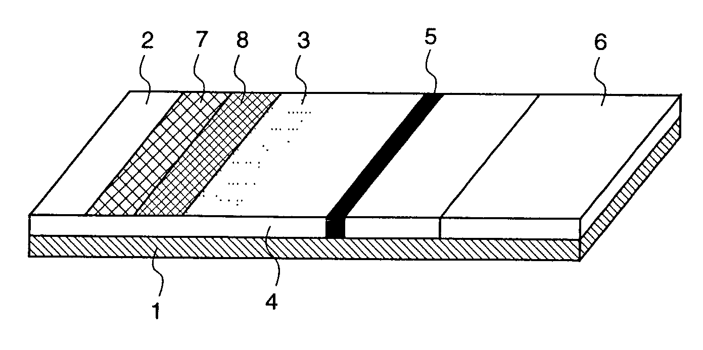
[0088]A first embodiment of the present invention will be described with reference to FIG. 1.

[0089]FIG. 1 is a perspective view illustrating the structure of a biosensor according to the first embodiment of the present invention.

[0090]In FIG. 1, numeral 1 denotes a reactive layer carrier support body composed of a liquid-impermeable material such as a plastic, which supports chromatography materials. Numeral 2 denotes a sample application area composed of a nonwoven fabric or glass fiber filter paper having high absorptivity, or the like, to which an inspection target solution is added or applied, numeral 8 denotes a bleaching reagent hold region where a bleaching reagent having the action of bleaching a blood pigment is held so as to be dissolved, numeral 3 denotes a marker hold region where a marker reagent is held so as to be dissolved, numeral 4 denotes a reactive layer made of nitrocellulose or the like, in which the sample is developed to cause a reaction, numeral 5 denotes a ...

embodiment 2

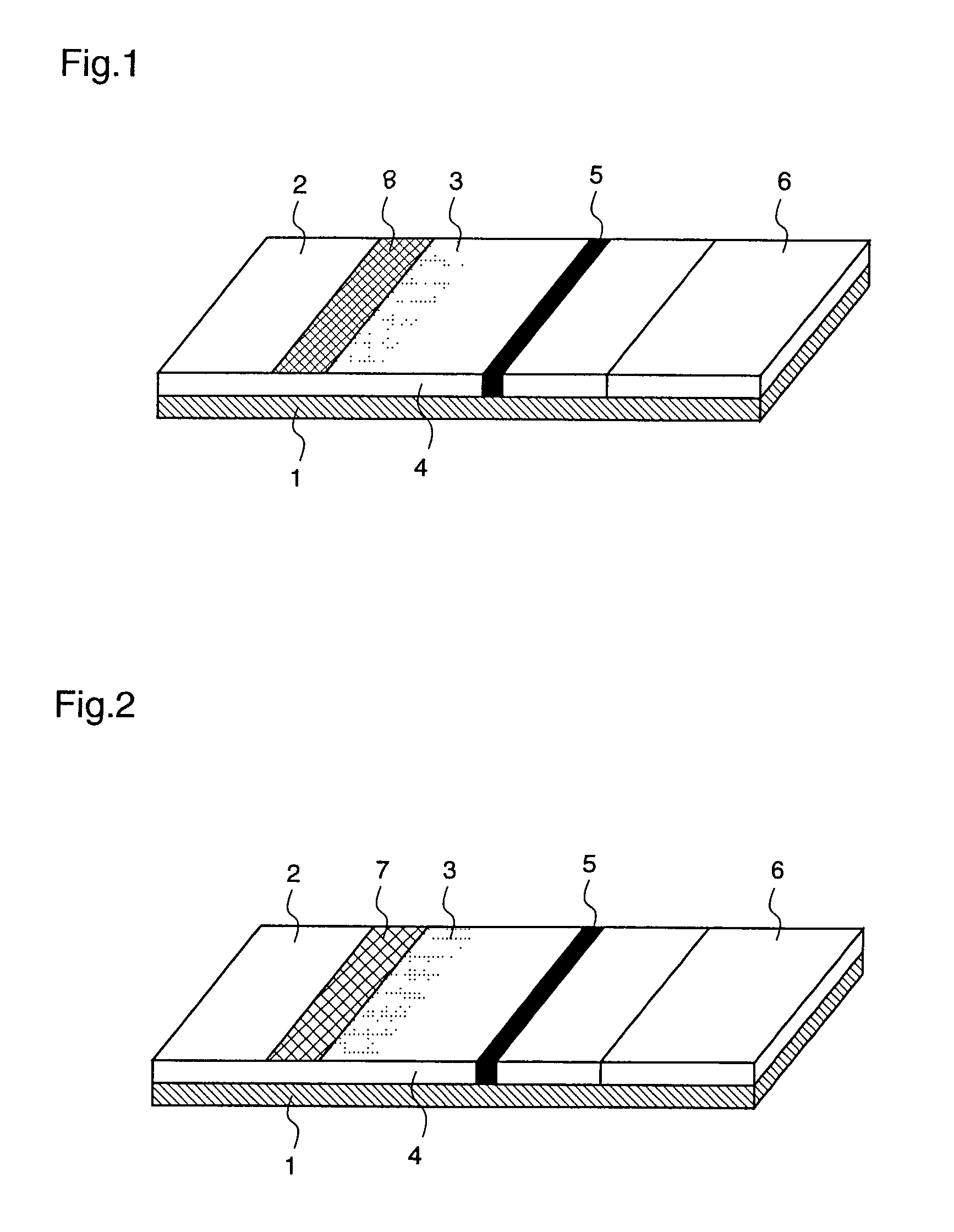
[0096]Hereinafter, a second embodiment of the present invention will be described with reference to FIGS. 2 and 3.

[0097]FIG. 2 is a perspective view illustrating the structure of a biosensor according to the second embodiment of the present invention, and FIG. 3 is a perspective view illustrating the structure of another biosensor according to the second embodiment of the present invention.

[0098]In FIGS. 2 and 3, numeral 7 denotes a contraction agent hold region where a cellular component contraction agent is held so as to be dissolved. With respect to other constitutions, the same regions as those shown in FIG. 1 will be denoted by the same reference numerals and their descriptions will be omitted. The respective regions of the sample application area 2, the marker hold region 3, the reactive layer 4, the specific protein immobilization part 5, the water absorbing area 6, the contraction agent hold region 7, and the bleaching reagent hold region 8 are formed being laminated or conn...

embodiment 3

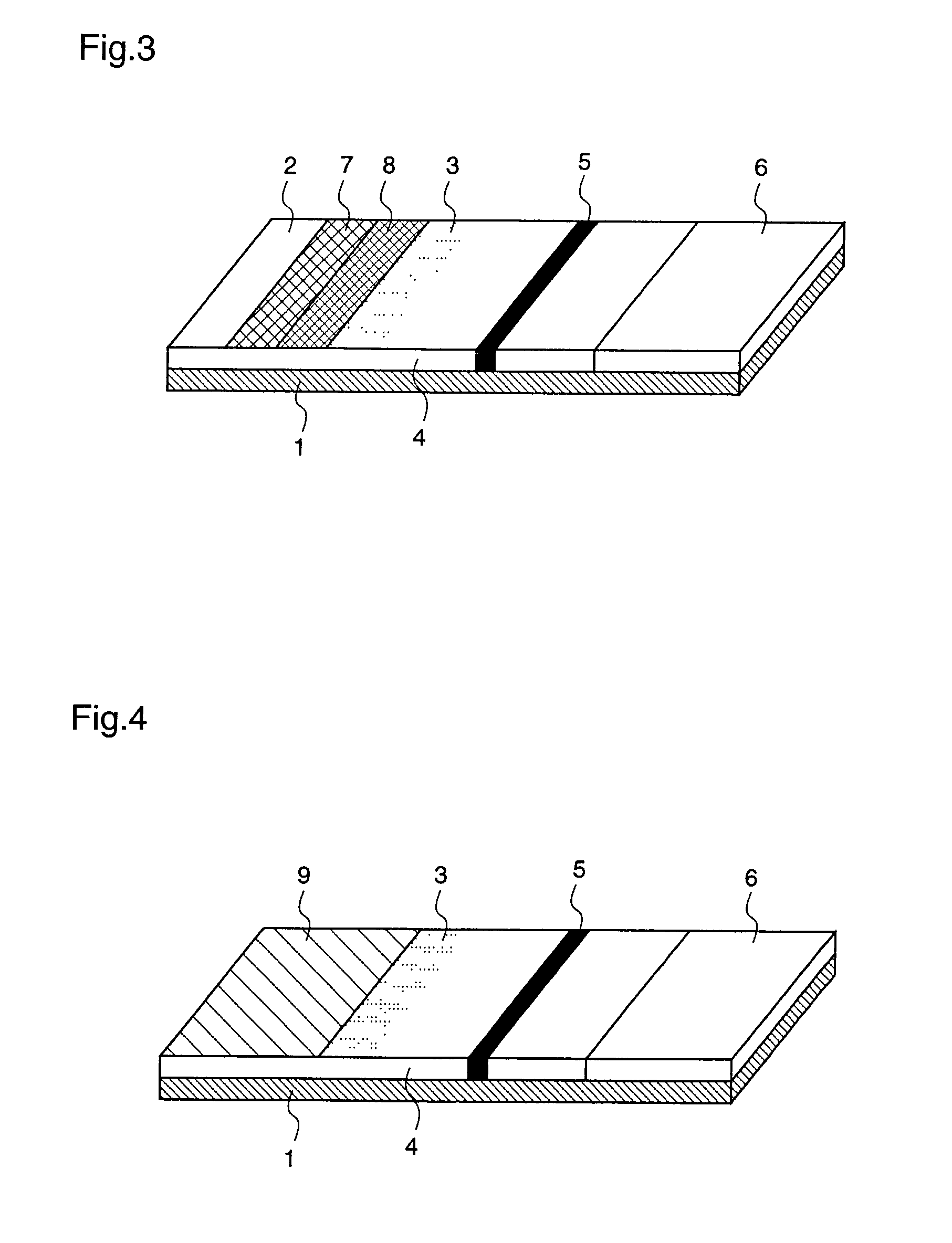
[0109]Hereinafter, a third embodiment of the present invention will be described with reference to FIGS. 4 and 5.

[0110]FIG. 4 is a perspective view illustrating the structure of a biosensor according to the third embodiment of the present invention, and FIG. 5 is a perspective view illustrating the structure of another biosensor according to the third embodiment of the present invention.

[0111]In FIG. 4, numeral 9 denotes a mixed reagent hold region where a mixed reagent of a cellular component contraction agent and a bleaching reagent is held so as to be dissolved. With respect to other constitutions, the same parts as those shown in FIG. 1 will be denoted by the same reference numerals and their descriptions will be omitted. The respective regions of the marker hold region 3, the reactive layer 4, the specific protein immobilization part 5, the water absorbing area 6, and the mixed reagent hold region 9 are formed on the reactive layer carrier support body 1.

[0112]In FIG. 5, numera...


PUM

PropertyMeasurementUnit
densityaaaaaaaaaa
diameteraaaaaaaaaa
widthaaaaaaaaaa

Abstract

A biosensor is provided with an area in which a reagent having bleaching action is carried in a state where it can be dissolved, at least in a part of a sample application area to which an inspection target solution is applied or the downstream of the sample application area in the direction of the inspection target solution permeating, in a development layer. In the so-constituted biosensor, a colored component in the inspection target solution can be faded by the bleaching reagent, so that the color in parts other than a reactive area is reduced in consequence, whereby a visual judgment is possible and a more accurate measurement result in which a reading error by a measuring device is extremely suppressed can be obtained.

Description

FIELD OF THE INVENTION[0001]The present invention relates to a biosensor and, more particularly, to a biosensor for analyzing constituents of blood.BACKGROUND OF THE INVENTION[0002]The structure of a conventional biosensor is shown in FIG. 16.[0003]FIG. 16 is a perspective view illustrating the structure of the conventional biosensor test strip.[0004]In FIG. 16, numeral 1 denotes a reactive layer carrier support body composed of a plastic or the like, which supports chromatography materials. Numeral 2 denotes a sample application area composed of a nonwoven fabric or glass fiber filter paper having high absorptivity, or the like, to which an inspection target solution is added or applied, numeral 3 denotes a marker hold region where a marker reagent is held so as to be dissolved, numeral 4 denotes a reactive layer made of nitrocellulose or the like, in which the sample is developed to cause a reaction, numeral 5 denotes a specific protein immobilization part in which a specific prot...

Claims


Application Information

Patent Timeline
Patent Type & Authority Patents(United States)
IPC IPC(8): G01N33/53G01N21/00G01N33/543G01N33/558
CPCG01N33/54306G01N33/54386G01N33/558Y10S436/81Y10S435/97Y10S435/805Y10S435/81G01N33/54387G01N33/54388
Inventor TAKAHASHI, MIENADAOKA, MASATAKATANAKA, HIROTAKAKITAWAKI, FUMIHISA
Owner PHC HLDG CORP
Why Eureka
Try Eureka