Apparatus for detecting the position of a probe element in a multi-coordinate measuring device

a multi-coordinate measuring and apparatus technology, applied in the direction of mechanical measuring arrangements, instruments, manufacturing tools, etc., can solve the problems of considerable effort involved in achieving the requisite measurement accuracy, and achieve the effect of less cost, precise accuracy and increased cos

Inactive Publication Date: 2006-10-03
KLINGELNBERG AG
View PDF28 Cites 10 Cited by
  • Summary
  • Abstract
  • Description
  • Claims
  • Application Information

AI Technical Summary

Benefits of technology

[0011]If in one configuration of the device of the invention the line grating array of the first standard includes the two-dimensional line grating and a one-dimensional line grating, any redundancy in the line grating array that could incur additional cost is avoided.
[0012]If in another configuration of the device of the invention the first position measuring system includes at least one first reading head and spaced therefrom a second reading head for detecting the line grating array of the first standard, with the reading heads being provided on the second standard opposite the main surface of the first standard, the location and the angular position of the second standard in relation to the line grating array provided on the first standard can be detected with precise accuracy. To detect the position in the XY plane even one reading head would suffice. The use of two reading heads arranged at a defined, sufficiently large distance to each other affords the added possibility of detecting the angular position about the Z axis.
[0013]If in a further configuration of the device of the invention either both reading heads of the two reading heads of the first position measuring system are associated with the two-dimensional line grating of the first standard or one reading head is associated with a one-dimensional line grating while the other reading head is associated with the two-dimensional line grating, the position measuring system can be configured more or less elaborately, as appropriate, because a reading head associated with a one-dimensional line grating is less costly than a reading head associated with a two-dimensional line grating.

Problems solved by technology

However, the effort involved in order to achieve the requisite measurement accuracy is considerable in this known shape measuring machine, in terms of both apparatus and measurement expenditure.
The support member is thus necessarily in touch with the reference standard, which thus forms a mechanical guide, which is always a disadvantage.

Method used


Image

  • Apparatus for detecting the position of a probe element in a multi-coordinate measuring device
  • Apparatus for detecting the position of a probe element in a multi-coordinate measuring device
  • Apparatus for detecting the position of a probe element in a multi-coordinate measuring device

Examples


Embodiment Construction

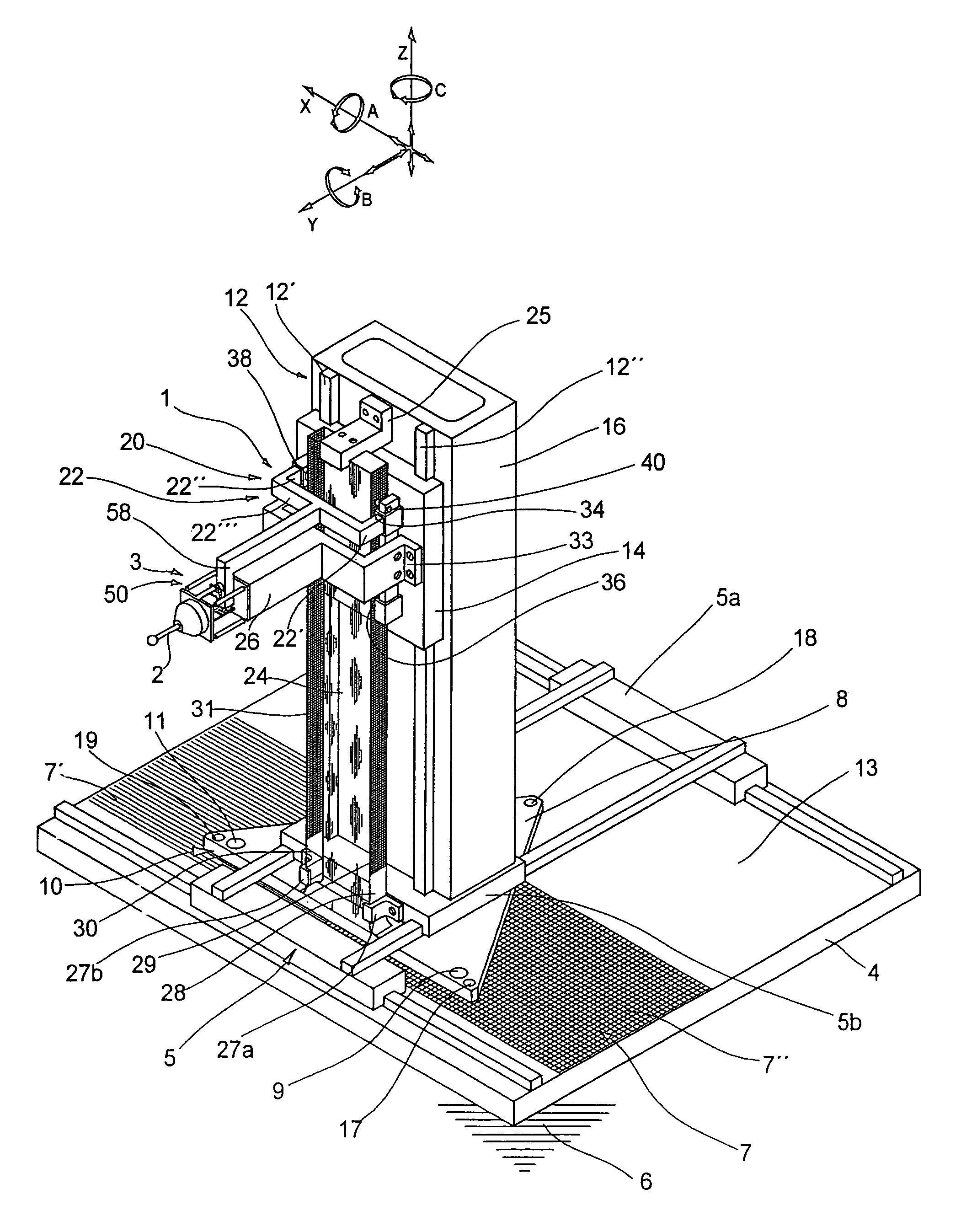
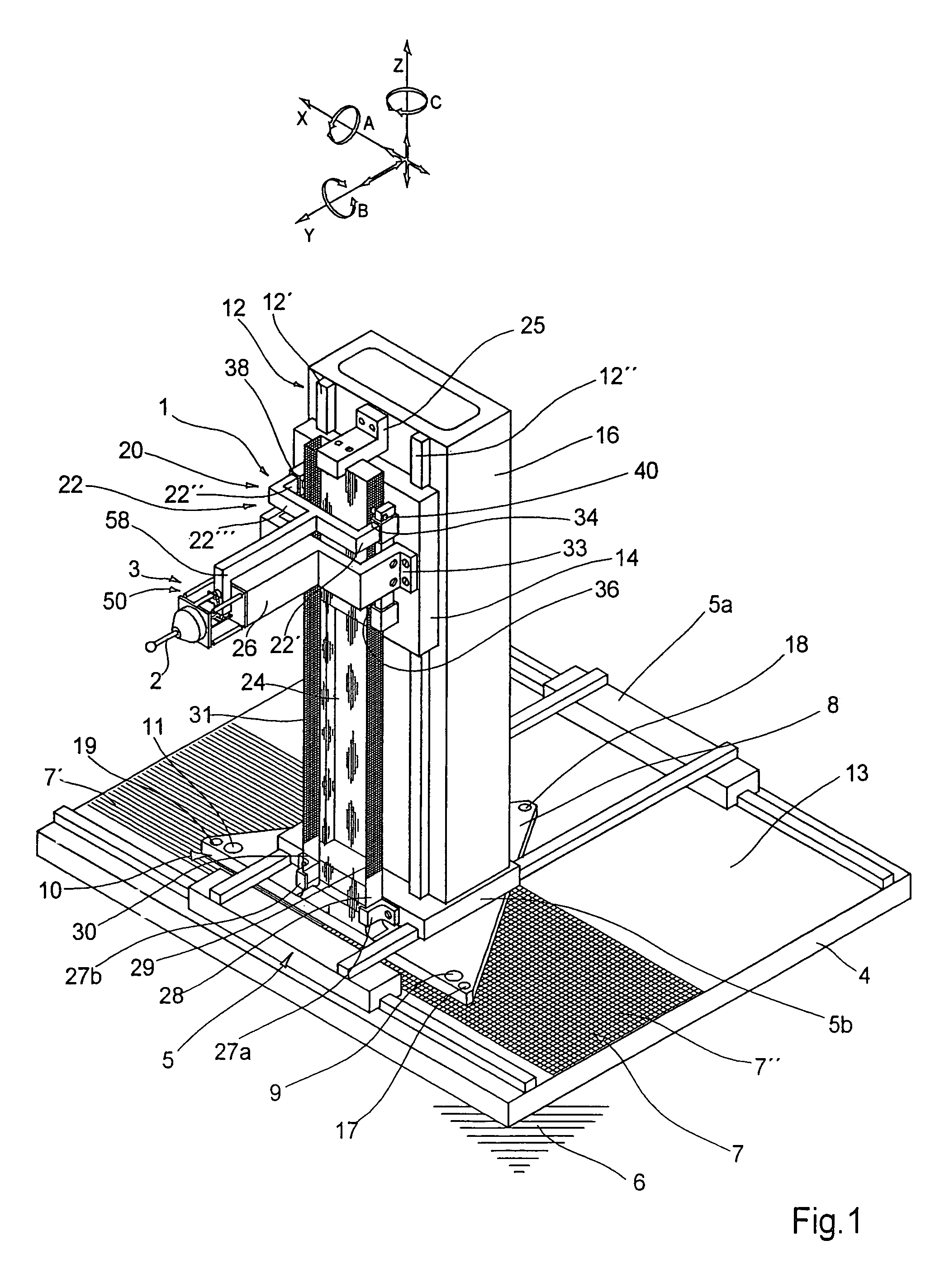
[0037]FIG. 1 shows a device, generally designated as 1, for direct detection of the spatial position of a probe element 2 in a multi-coordinate measuring apparatus of which only a Z column 16 and a three-dimensional probe assembly generally designated as 3 are shown. The Z column 16 is representative of the Z axis of a right-angled XYZ coordinate system illustrated at the top of FIG. 1. This illustration shows the six degrees of freedom of movement of a rigid body, that is, three translational degrees of freedom X, Y and Z and three rotary degrees of freedom A, B and C. The spatial position of a body is completely defined by the six degrees of freedom. The body whose spatial position is to be detected in the case herein described is as mentioned the probe element 2, which is part of the three-dimensional probe assembly 3 described in more detail further below. The aim is to detect any movements of the probe element 2 in X, Y and Z direction inclusive of all components of movement in...


PUM


Abstract

The invention is directed to a device for direct detection of the spatial position of a probe element in a multi-coordinate measuring apparatus, with a reference system comprised of at least one first standard and one second standard that are associated with coordinate axes of the measuring apparatus. The first standard is a planar standard with a line grating array. The second standard is non-contacting relative to the first standard and movable in two dimensions by means of a cross slide. Provision is made for a first position measuring system for determining the spatial position of the second standard with respect to the first standard, and for a second position measuring system for determining the spatial position of a carriage carrying a three-dimensional probe assembly, with respect to the second standard. The device forms in an associated multi-coordinate measuring apparatus a continuous measuring chain from the first standard to the tip of the probe element. This supplies directly a measurement result considering any guide inaccuracies, without the need to perform any path corrections.

Description

CROSS-REFERENCE TO RELATED APPLICATIONS[0001]This application is entitled to the benefit of and incorporates by reference essential subject matter disclosed in German Patent Application No. 10313038.1 filed on Mar. 24, 2003.FIELD OF THE INVENTION[0002]The present invention relates generally to a device for detecting the position of a probe element in a multi-coordinate measuring apparatus, and is more particularly directed to such a device having a reference system that includes first and second standards associated with the coordinate axis of the measuring apparatus.BACKGROUND OF THE INVENTION[0003]A shape measuring machine known from DE 43 45 094 C2 corresponds to a device of the type referred to in the foregoing, which machine includes a reference system of its own for path correction on guideways that is decoupled from the machine's guiding means and control devices and comprises dimensionally accurate elongate standards disposed in parallel alignment to the individual coordinat...

Claims


Application Information

Patent Timeline
Patent Type & Authority Patents(United States)
IPC IPC(8): G01B5/004G01D5/347G01B21/00G01B11/00
CPCG01B5/004G01B11/005
Inventor MIES, GEORG
Owner KLINGELNBERG AG
Why Eureka
Try Eureka