Switching control circuit for discontinuous mode PFC converters

Active Publication Date: 2006-10-03
SEMICON COMPONENTS IND LLC
View PDF3 Cites 107 Cited by
  • Summary
  • Abstract
  • Description
  • Claims
  • Application Information

AI Technical Summary

Benefits of technology

[0011]Furthermore, the switching control circuit includes a delay circuit for generating an inhibit signal in response to the turning off of the switching signal. The inhibit signal includes a delay time for postponing the turning on of the switching signal and limits the max

Problems solved by technology

However, the drawbacks of the foregoing approach are a higher power consumption of the resistor 21 and complexity of the control circuitry.
In addition, anoth

Method used


Image

  • Switching control circuit for discontinuous mode PFC converters
  • Switching control circuit for discontinuous mode PFC converters
  • Switching control circuit for discontinuous mode PFC converters

Examples


Example

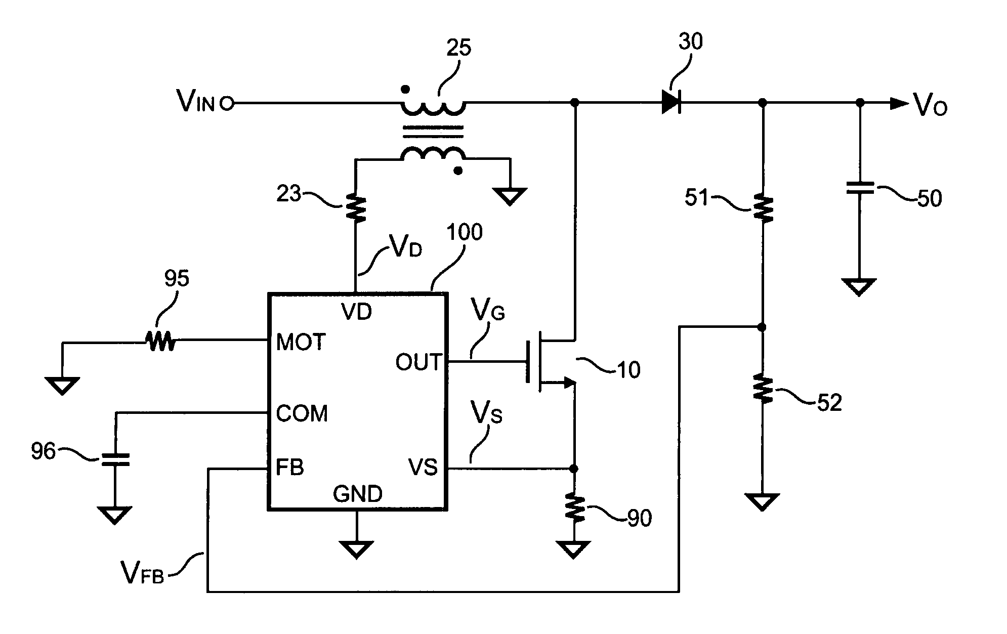
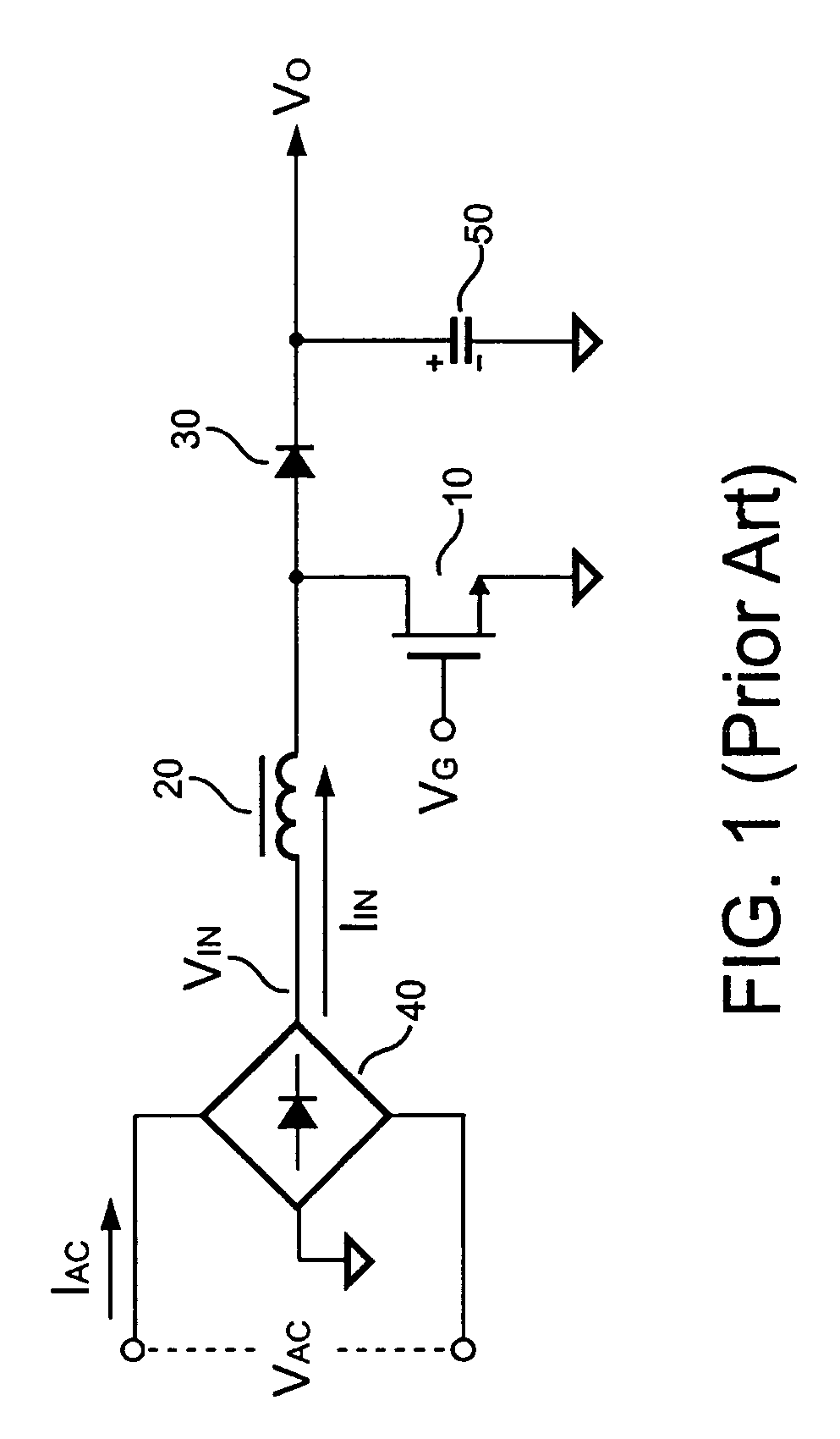
[0025]FIG. 7 is a schematic diagram of a PFC converter in discontinuous mode in accordance with an embodiment of the present invention. Using the PFC converter, an AC line input is converted to a DC output Vo, in which a transistor 10 controls the energy by switching an input voltage (VIN) via an inductor 25, a rectifier 30, and a capacitor 50. The purpose of the PFC is to control the current waveform of the AC line input as a sinusoidal waveform and to maintain the phase of the current to be the same as that of the line input voltage VAC. Through the rectification of the bridge, the VIN is always positive with respect to the ground of the PFC converter.

VIN(t)=Vp sin (ωt),

where Vp=√2×VIN (rms) and t=time;

The input current is similarly expressed as the following:

IIN(t)=Ip sin (ωt),

where Ip=√2×IIN (rms);

The input power of the PFC converter is then given by the following:

Pin=Vp×Ip / 2.

Taking the efficiency (η) into consideration in the equation, the output power is then given by the foll...


PUM


Abstract

A switching control circuit having detection terminal, input terminal, ramp generator, program terminal, error amplifier, mix circuit, and delay circuit for power factor control is provided. The detection terminal generates a detection signal in response to the inductor discharge. An input terminal is connected for detecting a switching current signal. The program terminal determines the slew rate of the ramp signal and the maximum on-time of the switching signal. An error amplifier generates an error signal for regulating the output. A mix circuit generates a mixing signal proportional to ramp signal and the switching current signal. The switching signal is turned on in response to the detection signal, and is turned off based on the error signal. The slew rate of the mixing signal is increased in response to the increase of the input voltage. The on-time of the switching signal is increased inversely proportional to the input voltage.

Description

FIELD OF INVENTION[0001]The present invention is related to power factor control (PFC), and more particularly to a control circuit for power factor control in discontinuous mode.BACKGROUND OF THE INVENTION[0002]Most power factor correction techniques incorporate a boost topology, which is operated in either continuous or discontinuous inductor current mode and is operated at a fixed or variable switching frequency. Due to a lower peak current, the continuous inductor current mode, which operated at a fixed switching frequency, is used for higher power applications. For lower power applications, the discontinuous inductor current mode, which is operated in a variable switching frequency, provides several advantages including smaller inductor size, lower costs, simpler circuitry, and zero current switching (ZCS).[0003]FIG. 1 illustrates a conventional PFC converter, in which a switching signal VG is connected to a transistor 10 to switch an inductor 20 and to control an input current ...

Claims


Application Information

Patent Timeline
IPC IPC(8): G05F1/40G05F1/10
CPCH02M1/4225Y02B70/126Y02B70/10
Inventor YANG, TA-YUNGCHEN, TSO MINTSU, PEI-SHENGSU, YING CHIEH
Owner SEMICON COMPONENTS IND LLC
Why Eureka
Try Eureka