Device for injecting cooling air into a turbine rotor

a technology of turbine rotor and cooling air, which is applied in the direction of machines/engines, stators, liquid fuel engines, etc., can solve the problems of major aerodynamic losses, unoptimized flow rate, and satisfactory results

Active Publication Date: 2006-10-10
SN DETUDE & DE CONSTR DE MOTEURS DAVIATION S N E C M A
View PDF8 Cites 10 Cited by
  • Summary
  • Abstract
  • Description
  • Claims
  • Application Information

AI Technical Summary

Benefits of technology

[0007]Thus, an object of the present invention is to provide a device for injecting cooling air into a turbomachine turbine rotor that provides high performance, is reliable, and inexpensive compared with prior art devices, and in particular that presents weight and costs that are reduced compared with those prior art devices. An object of the invention is also to conserve optimized aerodynamics even when not operating at maximum flow rate, thereby minimizing turbine efficiency losses, in particular during cruising flight.
[0009]Thus, this configuration which is simple to make and install does not add weight to the engine and presents operation that is particularly reliable since it is entirely passive.
[0013]Each injector is fixed to the inner and outer shrouds by a bolted connection so as to ensure a precise setting angle and each injector presents reduced height over a determined length adjacent to its trailing edge so as to leave the aerodynamic throat free to expand.

Problems solved by technology

Thus, the injection flow rate is not optimized in any way during cruising flight, for example, and there are therefore major aerodynamic losses associated with reintroducing excess cooling air both into the turbine blades and for the upstream purging.
Unfortunately, those solutions do not appear to be satisfactory since by adding mass to the engine (pipework, valves, etc.) they limit the performance of the turbomachine, and by making its equipment more complex (regulation) they limit reliability, and by adding components they increase costs.
In addition, those solutions do not enable optimized aerodynamics to be conserved for all stages of flight, and in particular during the main or cruising stage.

Method used


Image

  • Device for injecting cooling air into a turbine rotor
  • Device for injecting cooling air into a turbine rotor
  • Device for injecting cooling air into a turbine rotor

Examples


Embodiment Construction

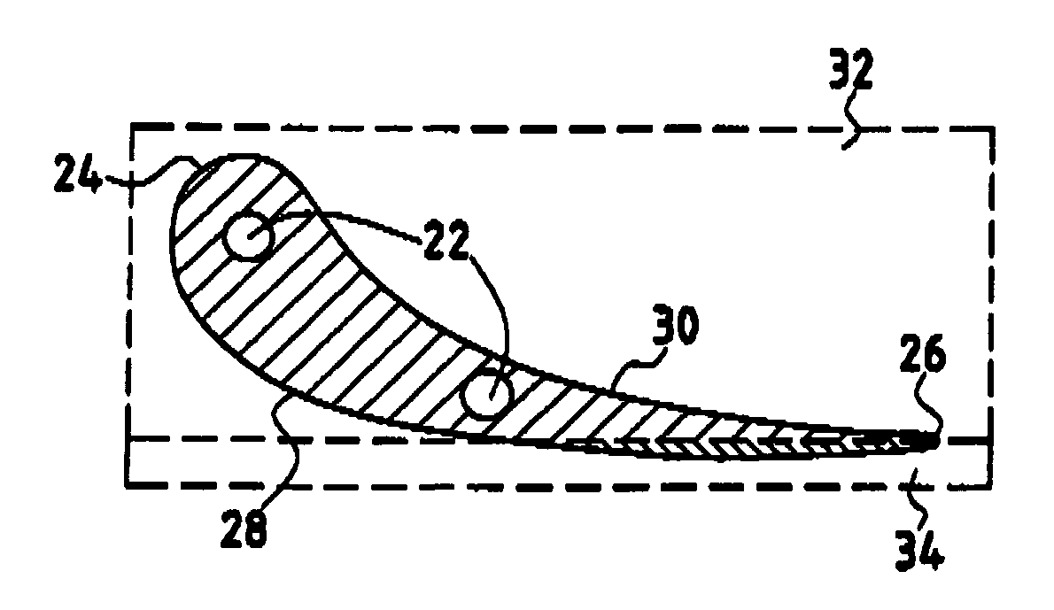
[0022]It is known that the flying speed of an airplane has an influence on the temperature of the air passing through the turbomachine. In particular, the temperature difference between takeoff and cruising is typically 100 Kelvins (K) to 200 K at the injectors feeding the moving blades. The inventors have taken advantage of this characteristic by proposing injectors having an aerodynamic profile that varies with temperature, thus enabling the turbine rotor to be overventilated on takeoff, to be ventilated exactly right during cruising, and to be ventilated at the strict minimum while idling.

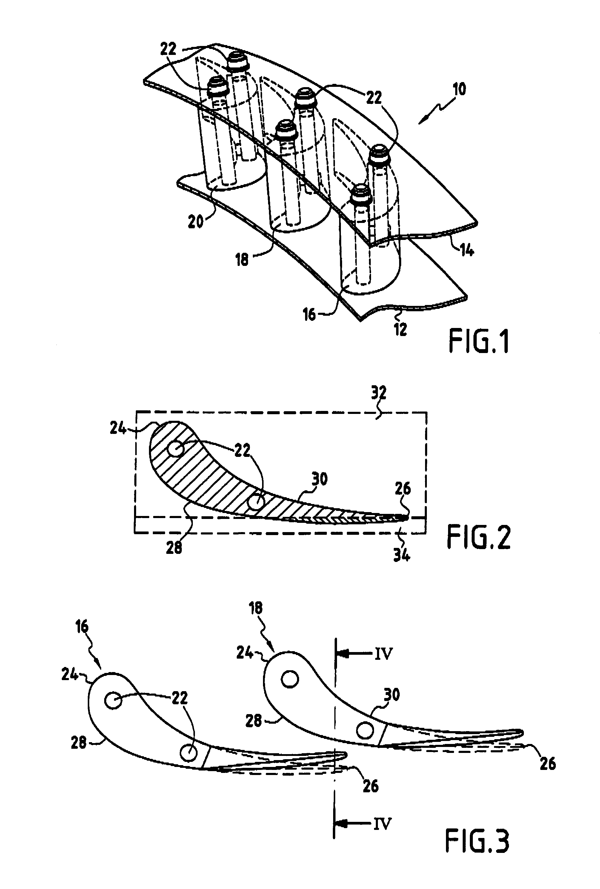
[0023]A device of the invention for injecting cooling air into the rotor of a turbomachine turbine is shown diagrammatically in a fragmentary perspective view in FIG. 1.

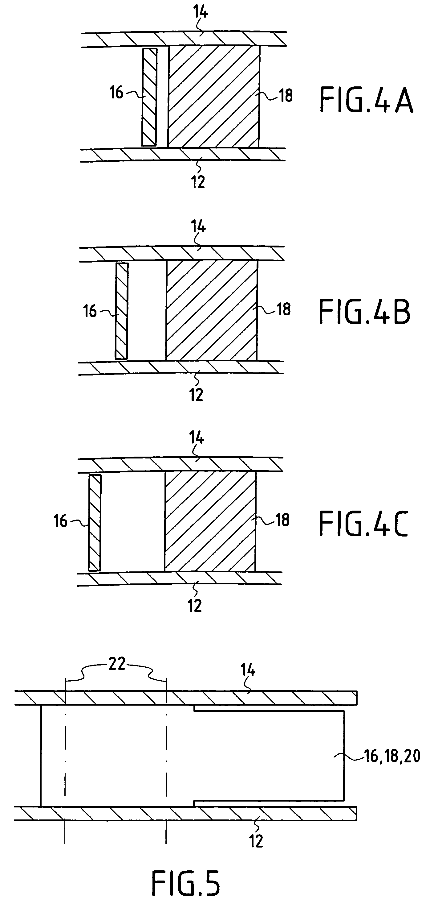
[0024]The device 10 comprises an inner shroud 12 and an outer shroud 14, together with a plurality of injectors 16, 18, 20 regularly distributed about a longitudinal axis of the turbomachine and each in the same determined positi...


PUM


Abstract

A device for injecting cooling air into a turbo-machine turbine rotor includes a plurality of injectors distributed regularly around a longitudinal axis of the turbomachine and mounted between an inner shroud and an outer shroud. Each injector has a bimetallic structure with a first metal material forming a major portion of the structure of the injector and having a first coefficient of thermal expansion, and a second metal material forming a complementary portion of the structure in the vicinity of the suction side wall meeting the trailing edge of the injector, and having a second coefficient of thermal expansion that is smaller than the first.

Description

FIELD OF THE INVENTION[0001]The present invention relates in general to systems for injecting cooling air into airplane turbomachines, and it relates more particularly to optimizing the feed of cooling air to a turbine rotor.PRIOR ART[0002]A conventional system for injecting cooling air into a turbine rotor of an airplane turbomachine is shown diagrammatically in FIG. 7. The rotor 40 has through orifices 42 regularly distributed around a longitudinal axis 44 of the turbomachine and through which cooling air is injected. The cooling air comes from a flow of cooling air 46 taken from around the combustion chamber 48, for example, and it is injected from stationary injectors 50 distributed circumferentially around the longitudinal axis, with the mean radius of the injectors corresponding to the mean radius of the through orifices of the rotor so that the injectors face the orifices. The injection flow that serves to cool the turbine blades 52 and also the rotor disk 54 and the labyrint...

Claims


Application Information

Patent Timeline
Patent Type & Authority Patents(United States)
IPC IPC(8): F01D17/14F01D5/08F01D5/14F01D9/02F01D9/06F01D17/16
CPCF01D5/085F01D5/148F01D9/02F01D9/065F01D17/16Y02T50/671Y02T50/673Y02T50/676F05D2300/50212Y02T50/60
Inventor MORTGAT, DIDIER
Owner SN DETUDE & DE CONSTR DE MOTEURS DAVIATION S N E C M A
Why Eureka
Try Eureka