Single polarization optical fiber laser and amplifier

Inactive Publication Date: 2006-10-10
CORNING INC
View PDF25 Cites 24 Cited by
  • Summary
  • Abstract
  • Description
  • Claims
  • Application Information

AI Technical Summary

Benefits of technology

[0020]Preferably, air or vacuum filled holes are positioned close to an elliptical core of the linearly birefringent and linearly dichroic optical waveguide such that the waveguide exhibits a differential polarization dependent loss (PDL) greater than 70 dB in the wavelength band of single polarization operation. The op

Problems solved by technology

However, the noncircular geometry and the associated stress-induced birefringence alone are, generally, not sufficient to maintain the desired

Method used


Image

  • Single polarization optical fiber laser and amplifier
  • Single polarization optical fiber laser and amplifier
  • Single polarization optical fiber laser and amplifier

Examples


Example

[0105]The above example 1–18 illustrates the sensitivity of the PZ fiber 30 to various structural parameter changes. In particular, it can be seen in Examples 1–4 that by changing the hole diameter from 1 to 15 microns, the single polarization wavelength band may be driven to shorter wavelengths. Examples 14–18 dramatically illustrates how the core delta, Δ1, may be used to broaden the width of the single polarization band. The remaining examples show how the average core diameter, d avg, and aspect ratio, AR1, may be used to influence the single polarization bandwidth and the relative location of that band.

[0106]The fiber parameters discussed so far are not the only possible design of the fiber. A passive single-polarization fiber has several design parameters such as the ellipticity of the core, the dimensions of the core, the core delta, the size of the adjacent holes for optimization for different applications. One can design these fiber parameters to achieve differential cut-of...

Example

EXPERIMENTAL EXAMPLE 1

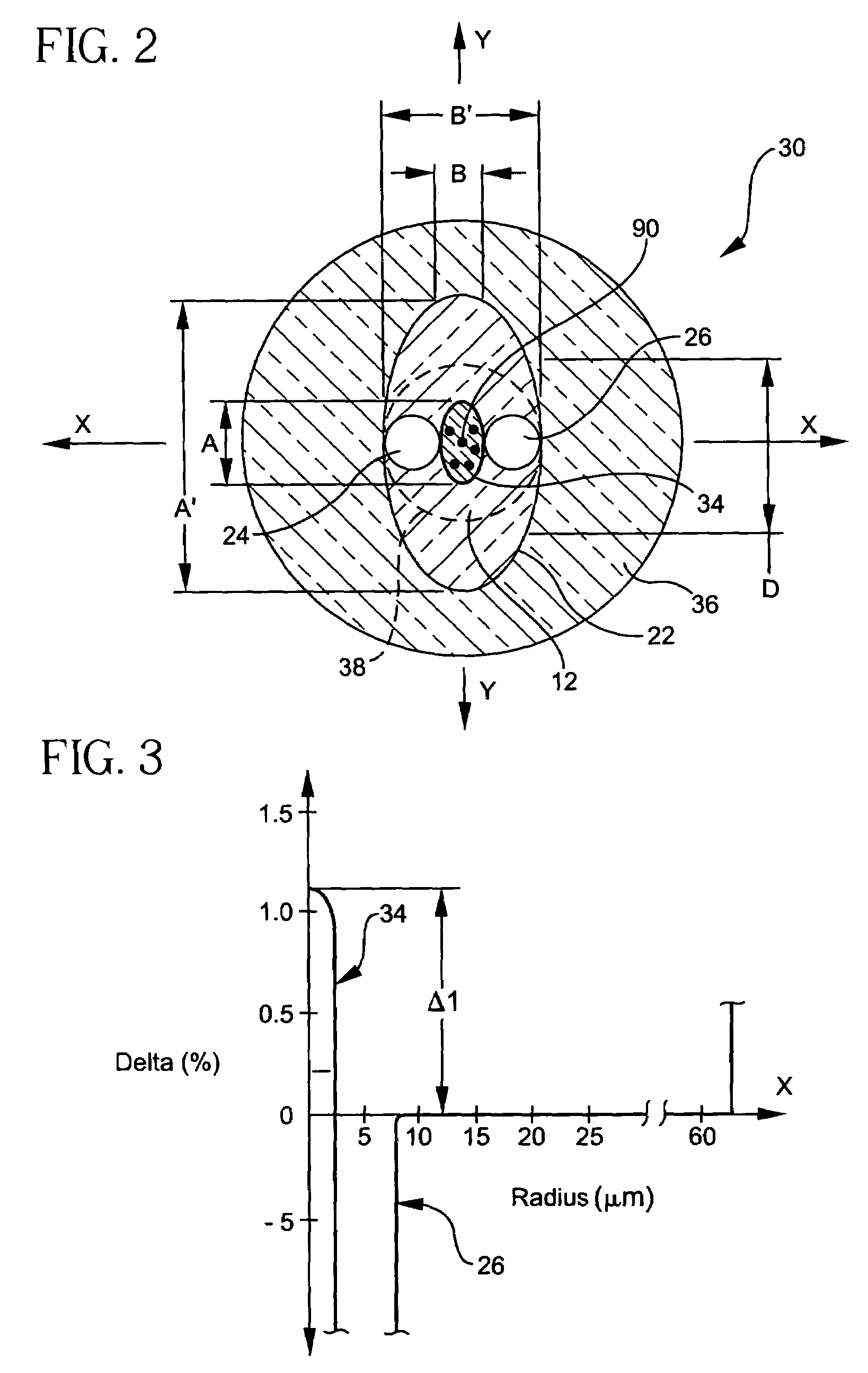
[0118]A first representative single polarization fiber 30 according to the invention was manufactured having the cross-sectional structure shown in FIG. 7. The fiber 30 has a central core 34 having an average diameter, d avg, of about 5.33 microns, a maximum dimension, A, of about 7.75 microns, a minimum dimension, B, of about 2.9 microns—resulting in a first aspect ratio A / B equal to about 2.7, a central core delta, Δ1, of 1.1%, and an alpha profile having an α of about 2. The holes 24, 26 were partially included in the annular region 12 and partially included in the cladding 22. Holes 24, 26 had an average diameter of about 8.3 microns. The annular region 12 was fluorine-doped thereby being depressed relative to the pure silica cladding 22. The relative refractive index, Δ2, of the annular region 12 was −0.4% and the outer diameter D of the annular region 12 was about 16 microns. The holes 24, 26, in this embodiment, substantially abutted the sides of the cen...

Example

EXPERIMENTAL EXAMPLE 2 AND 3

[0119]Other portions of the same fiber along the length thereof (and spaced from the length of Exp. Ex. 1) were also tested in Exp. Ex. 2 and 3 giving slightly different performance results. It was determined by the inventors that this variation in properties along the length of the fiber was due predominantly to process control variations in the prototype fiber which in a production fiber would be in much better control.


PUM

PropertyMeasurementUnit
Lengthaaaaaaaaaa
Lengthaaaaaaaaaa
Sound / signal amplitudeaaaaaaaaaa

Abstract

An optically active linear single polarization device includes a linearly birefringent and linearly dichroic optical waveguide (30) for propagating light and having single polarization wavelength range (48). A plurality of active dopants are disposed in a portion (34) of the linearly birefringent and linearly dichroic optical waveguide (30) for providing operation of the waveguide in an operating wavelength range (650) for overlapping the single polarization wavelength range (48).

Description

[0001]This patent application is related to patent application 60 / 479,892, filed Jun. 19, 2003 with and assigned to the same assignee.[0002]Parts of this invention were made with Government support under Agreement No. MDA972-02-3-004 awarded by DARPA. The Government may have certain rights in some of the claims of the invention.BACKGROUND OF THE INVENTION[0003]1. Field of the Invention[0004]The present invention relates generally to optically active devices, and more particularly to a single polarization optical fiber laser or amplifier.[0005]2. Technical Background[0006]Rare-earth doped fiber lasers such as ytterbium-doped fiber lasers are finding uses in such areas as materials processing, product marking and engraving, and micromachining. Ytterbium-doped fiber lasers operating with high-power, narrow linewidth, and high pulse energy are being developed. The application space of fiber lasers would be broadened by the availability of additional operating wavelengths and even higher...

Claims


Application Information

Patent Timeline
IPC IPC(8): G02B6/02G02B6/10H01S3/00H04B10/12G02B6/00C03B37/012C03B37/027G02B6/028H01S3/063H01S3/067H04B10/00
CPCC03B37/01217C03B37/02781G02B6/105H01S3/067C03B37/01225H01S3/0675C03B2201/34C03B2203/14C03B2203/30C03B2205/08C03B2205/10G02B6/02G02B6/0281G02B6/03627G02B6/03655G02B6/03694H01S3/063H01S3/06729
Inventor BERKEY, GEORGE E.LI, MING-JUNNOLAN, DANIEL A.WALTON, DONNELL T.ZENTENO, LUIS A.
Owner CORNING INC
Why Eureka
Try Eureka