Digital systolic array architecture and method for computing the discrete Fourier transform

a digital systolic array and transform technology, applied in the field of systems and methods for computing a discrete fourier transform, can solve the problems of difficult to translate into vlsi hardware, inability to compute dfts with limited choices in the number of transform points, and inability to operate quickly enough for many applications, etc., to achieve high throughput and low latency

Inactive Publication Date: 2006-10-10
NASH JAMES G
View PDF8 Cites 16 Cited by
  • Summary
  • Abstract
  • Description
  • Claims
  • Application Information

AI Technical Summary

Benefits of technology

[0019]A further objective is to provide a system and method as aforesaid whereby the structure of the systolic array can be selected to be hardware efficient, and / or scalable, and / or have a high throughput and low latency.

Problems solved by technology

A general purpose computer can be programmed to provide this computation but due to the architectural limitations thereof does not operate quickly enough for many applications.
Thus, they are irregular and difficult to translate into VLSI hardware.
In addition they are only able to compute DFTs with limited choices in the number of transform points.
For the most part, the prior art for determining a DFT is not able to utilize or fully benefit from systolic processing structures that permit simultaneous operation of multiple processors to find the DFT by operating on smaller parts of the problem in parallel.
However, specialized prior art systolic arrays for computing the DFT, either directly or via FFT techniques require excessive arithmetic hardware, especially for large transform sizes, and are slow both in terms of computational latency (time to do a single DFT computation) and computational throughput (time between successive DFT computations).
Prior art non-systolic arrays for computing DFTs or FFTs have utilized an irregular design structure that is not scalable.
Because the structure of the prior art circuits is irregular, it is not practical to utilize the same prior designs, only with increased size, to produce a new circuit that would compute a DFT with a different transform length, i.e., the design is not scalable.
Therefore, design costs for a specialized application of a non-systolic array remain high because an entirely new design is generally required any time the transform length is changed.
Moreover, prior art non-systolic array designs for computing DFTs are severely limited in application because the transform length which they can calculate has to satisfy the restriction N=rm where N is the transform length, r is the radix, and m is an integer.
This exponential restriction significantly limits the practical transform lengths that can be computed, especially for large transform sizes.
Many prior art non-systolic designs use r=4 because this permits significant arithmetic simplification, but practical transform lengths are even more severely limited.
Systolic array designs have been more costly to implement in the prior art for computing DFTs at least in part because they require at least the same number of fixed point complex multipliers as the transform length to be computed.
Complex fixed point multiplier processing elements are more costly than complex fixed point adders because they consume considerably more chip area and power.
But working with two floating point numbers adds considerable complexity, because the exponents have to be compared and “aligned”, which involves a shift of one of the words.
Consequently, floating point processing elements have considerable additional complexity that makes them less desirable for in multiple processor applications.
Moreover, the processing elements in prior art systolic array designs often have to be capable of performing both adding and multiplying functions thereby further increasing the cost and circuit area of implementation.
The non-systolic prior art designs discussed above for computing DFTs are irregular, non-scalable, difficult to design, and costly to implement.
Prior art systolic designs are more costly and less efficient.
Prior art systolic systolic designs have not been able to take advantage or radix-4 structures or other bases.
The prior art systolic designs require more complicated processing elements that are required to multiply and add.

Method used


Image

  • Digital systolic array architecture and method for computing the discrete Fourier transform
  • Digital systolic array architecture and method for computing the discrete Fourier transform
  • Digital systolic array architecture and method for computing the discrete Fourier transform

Examples


Embodiment Construction

The DFT is defined as

[0049]Z⁡[k]=∑n=1N⁢X⁡[n]⁢ⅇ-j⁡(2⁢⁢π / N)⁢(k-1)⁢(n-1)k=1,2⁢⁢…⁢⁢N(1)

where X[n] are the time domain input values and Z[k] are the frequency domain outputs. It is convenient to represent (1) in the matrix terms

Z=CX  (2)

where C is a coefficient matrix containing elements WNkn=e−2*j*π*(n−1)*(k−1) / N. In order to transform C into the desired base-b format it is necessary to find a permutation matrix P that reorders X and Z according to

[0050]Xb=4=P⁡[X1X2X3X4X5⋮X13X14X15XN]=[X1X1+N / 4X1+N / 2X1+3⁢N / 4X2⋮XN / 4XN / 2X3⁢N / 4XN],and⁢⁢Zb=4=P⁢⁢Z⁢.(3)

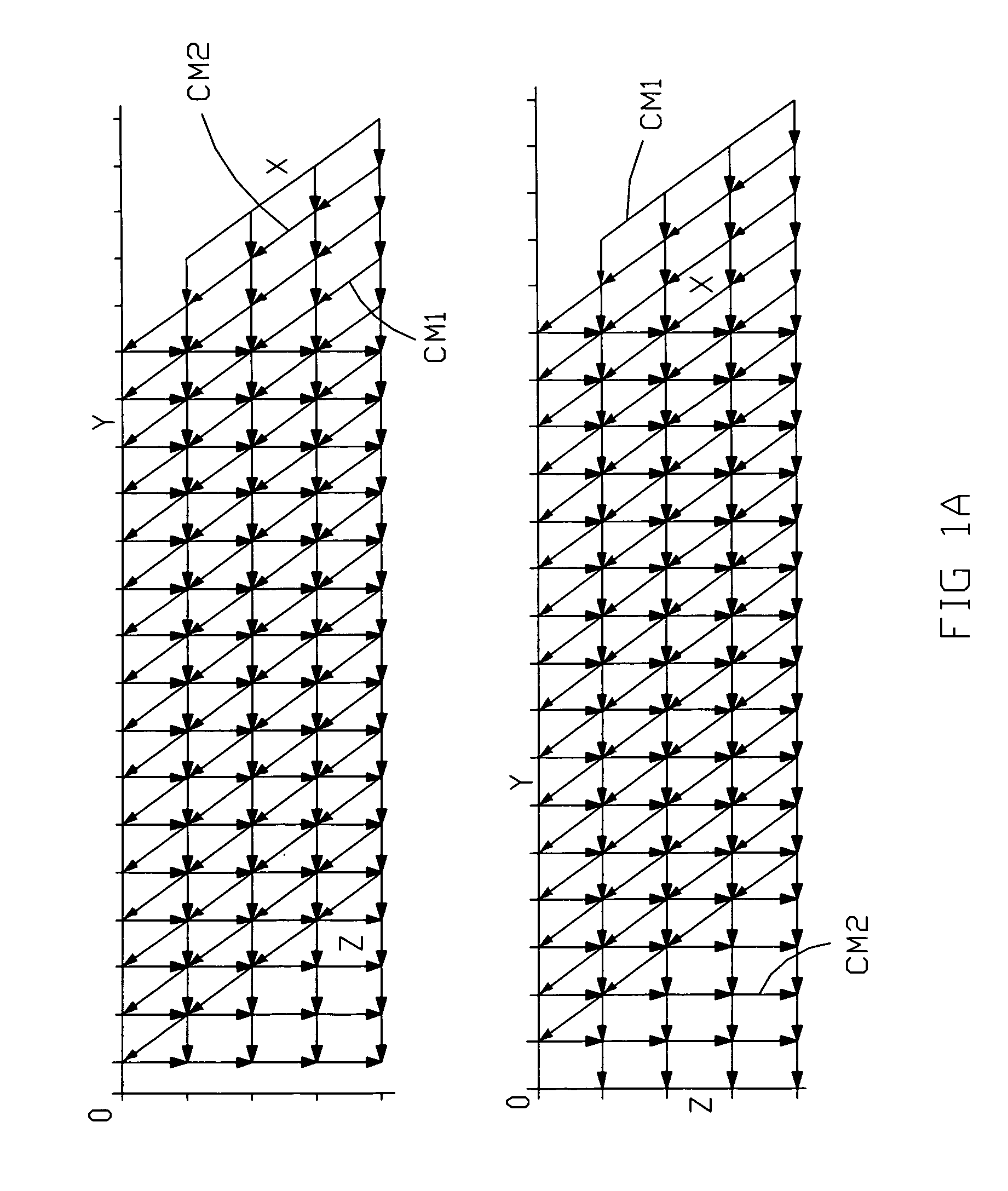
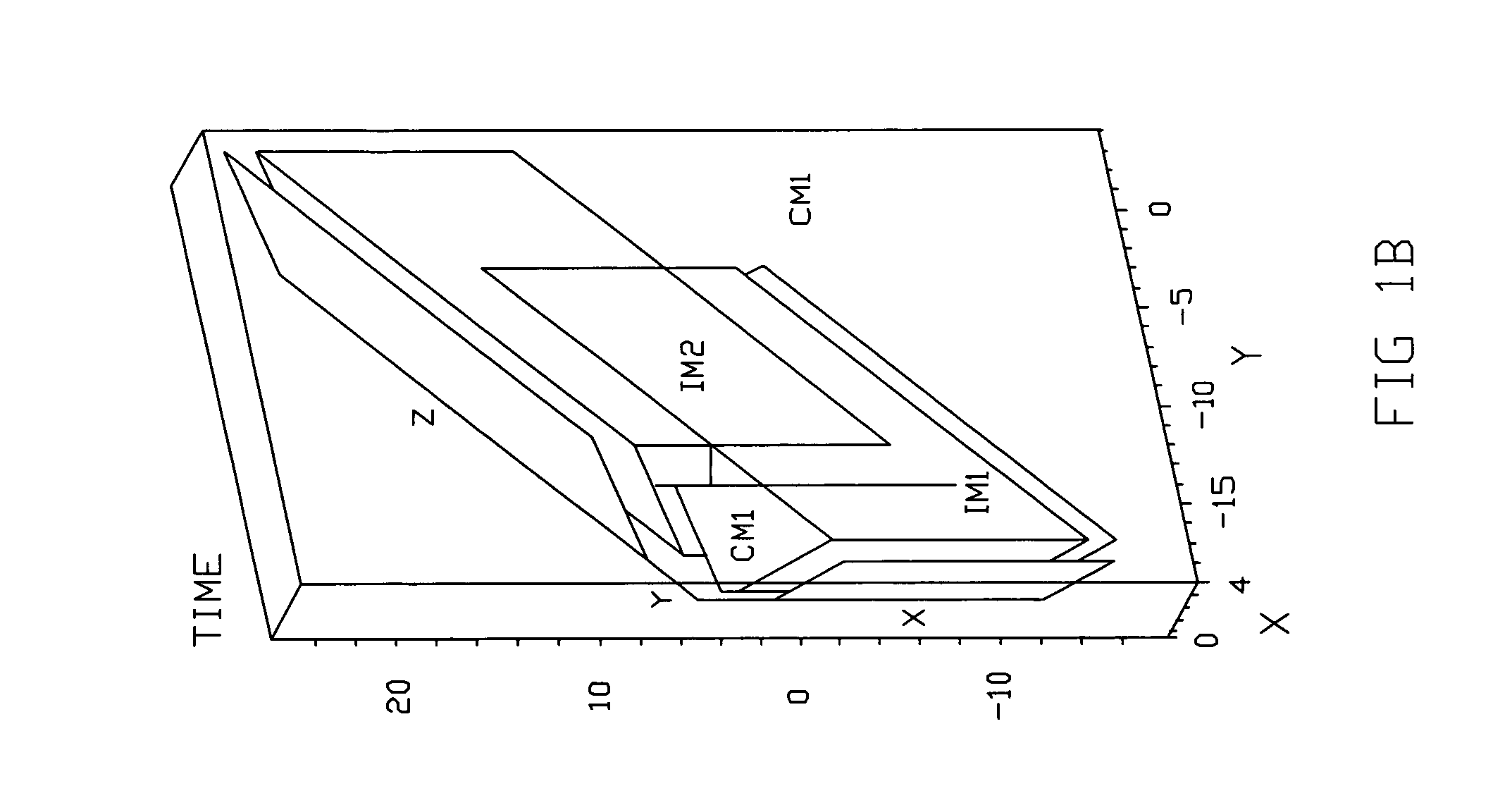
With this value of P, C can be transformed into Cb=PCPt, so that Zb=CbXb. This transformation allows Cb to be written as an (N / b)×(N / b) array of b×b blocks, each block C[i,j] specified by

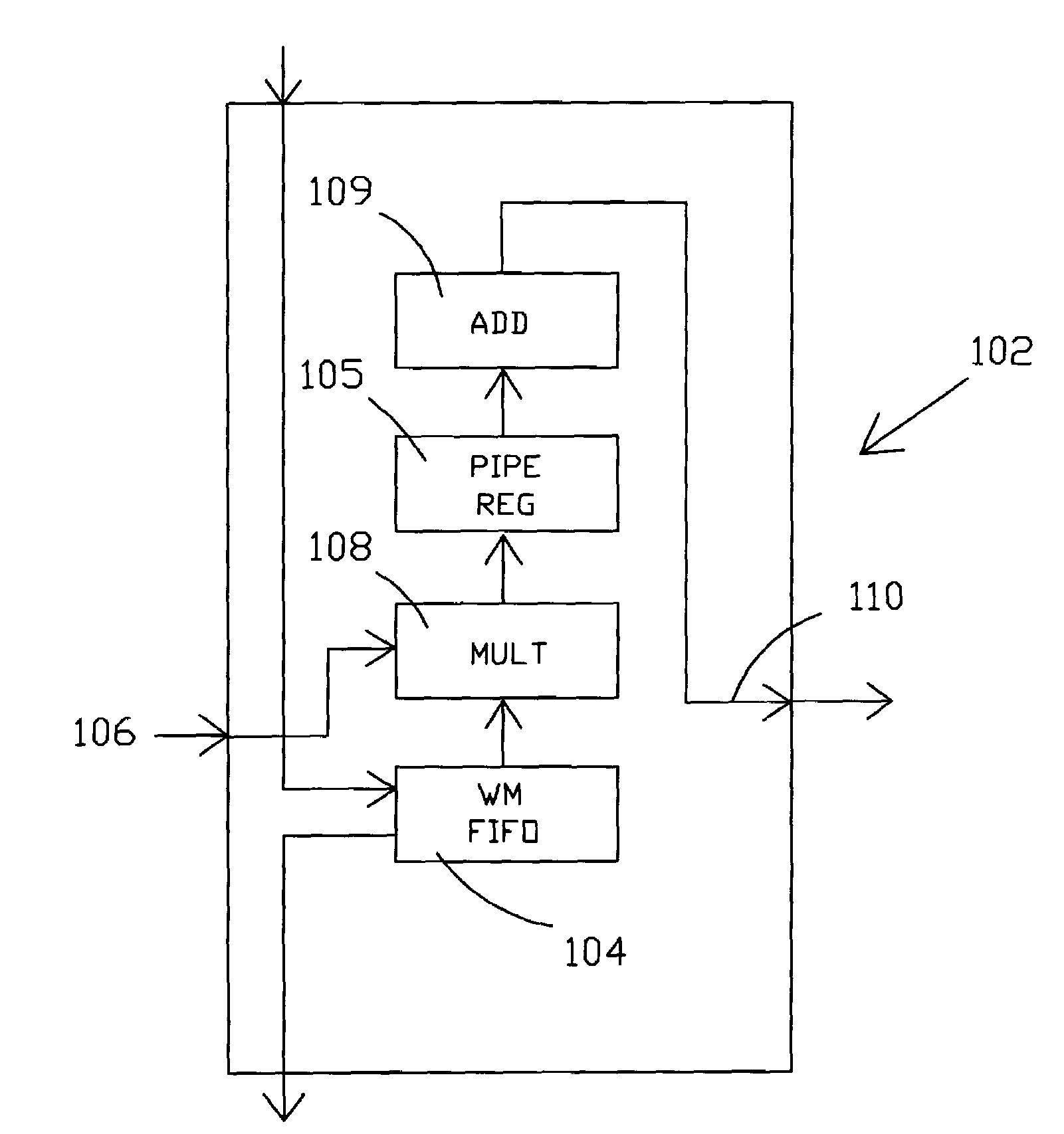
CM[i,j]=WM[i,j]*cD((j−1)mod(b))+1C((i−1)mod(b))+1  (4)

where cDi=citI with ci a b-element vector, Ci is a b×b matrix, each row being cit, and WM[i, j] is an element in the (N / b)×(N / b) matrix,

[0051]WM=[1111⋯1W1W2W3⋯1W2W4W6⋯1W3W6W9⋯⋮⋮⋮⋮⋰]⁢.(5)

[0052]With this block...


PUM


Abstract

A more computationally efficient and scalable systolic architecture is provided for computing the discrete Fourier transform. The systolic architecture also provides a method for reducing the array area by limiting the number of complex multipliers. In one embodiment, the design improvement is achieved by taking advantage of a more efficient computation scheme based on symmetries in the Fourier transform coefficient matrix and the radix-4 butterfly. The resulting design provides an array comprised of a plurality of smaller base-4 matrices that can simply be added or removed to provide scalability of the design for applications involving different transform lengths to be calculated. In this embodiment, the systolic array size provides greater flexibility because it can be applied for use with any transform length which is an integer multiple of sixteen.

Description

[0001]This application claims the benefit of U.S. Provisional Patent Application No. 60 / 380,494 filed May 14, 2002.BACKGROUND OF THE INVENTION[0002](1) Field of the Invention[0003]The present invention relates generally to systems and methods for computing a discrete Fourier transform and, more particularly, to systems and methods for designing and providing systolic array architectures operable for computing the discrete Fourier transform or fast Fourier transform.[0004](2) Description of the Prior Art[0005]Computational schemes for computing the discreet Fourier transform (DFT) have been intensively studied because of their central importance to many digital signal processing applications. A general purpose computer can be programmed to provide this computation but due to the architectural limitations thereof does not operate quickly enough for many applications. Specialized processing circuits are therefore frequently used for this purpose. Such specialized processing circuits of...

Claims


Application Information

Patent Timeline
Patent Type & Authority Patents(United States)
IPC IPC(8): G06F17/14
CPCG06F17/141G06F17/142
Inventor NASH, JAMES G.
Owner NASH JAMES G
Why Eureka
Try Eureka