
Remote sensing and signaling of the presence of wildfire

a remote sensing and wildfire technology, applied in the field of remote sensing and signaling of the presence of wildfire, can solve the problems of increasing the danger of wildfire, quickly overwhelming any available resources, and no homeowner can be constantly on the lookout, so as to enhance the detection response to the wildfire

Inactive Publication Date: 2006-10-17
SMITH ROBERT J
View PDF5 Cites 19 Cited by
  • Summary
  • Abstract
  • Description
  • Claims
  • Application Information

AI Technical Summary

Benefits of technology

"The patent describes an apparatus for detecting the presence of a wildfire or electrical arc using a UV sensor. The sensor produces a pulse output that tracks a trend in UV radiation, which is emitted by the fire or arc. The sensor is designed to be sensitive to the UV radiation and extraneous noise sources, such as sunlight or other sources of UV radiation. The apparatus includes a light sensor that generates an intermediate output that tracks the pulse output, regardless of the increase in the number of pulses caused by extraneous sources. The intermediate output is used to generate an alarm signal. The apparatus can be used to detect the presence of a wildfire or electrical arc in a structure, providing early detection and alerting for fire protection."

Problems solved by technology

As more residences are built in forested parts of the country, the danger of wildfire becomes ever more ominous due to the number of lives and properties that are at risk.
Without early detection, such a fire can quickly overwhelm any resources available to fight the fire.
However, no homeowner can be constantly on the lookout for wildfires, particularly at night.
It is well known that wildfires may grow exponentially in dry weather, steep terrain or in high winds.
Due to the exponential growth of wildfires, a wildfire must be attacked early or it quickly grows too large and hazardous for a direct attack.
High winds are additionally dangerous since they often initiate power line arcing, which may cause the power line to break and fall to the ground, thereby immediate setting light fuels on fire.
Then, fire crews may wet down areas downwind of an arcing wire before a fire has begun.
However, various other warm or hot objects, such as the sun or its reflections, also emit large quantities of infrared radiation.
Since the signal processing for such an array-type infrared detector is complex, these systems are generally expensive.
Furthermore, these infrared detection systems are ineffective in detecting electrical arcs, which have low infrared emissions.
Also, although some bands of the infrared spectrum (such as the 2.7 μm, 4.3μm and 6.5μm bands) are “solar blind” to some extent because the atmosphere blocks sunlight at those wavelengths and thereby prevents these solar wavelengths from reaching the ground, the usefulness of these infrared detectors in long-distance wildfire detection is limited since the atmosphere also blocks these wavelengths when they are emitted by a fire.
Moreover, currently available UV detectors are limited in usefulness in sunlight because the sun also radiates ultraviolet radiation.
However, most UVC radiation is blocked by tropospheric atmosphere, particularly by oxygen.
Unfortunately, ideal detectors which operate in this limited ultraviolet radiation range are not currently available.
While highly effective, absorptive bandpass filters of cobalt glass are available, no such filter is currently available with such exacting specifications.
As an alternative, interference filters may be designed to specifically pass only wavelengths between 240nm and 270nm, but interference filters are expensive, have limited field of view (i.e., exhibits high angle sensitivity) and generally do not provide sufficient wavelength rejection at wavelengths longer than 280 nm.
The angle sensitivity is particularly problematic in fire detection since it is desirable to have one detector to cover a large angular field of view.
However, the UVB rejection of such photodiodes thus far has been limited to approximately 30 dB.
Very few detectors can meet such UVB rejection requirements, and still fewer achieve such values of UVB radiation rejection over a hemispherical field of view.
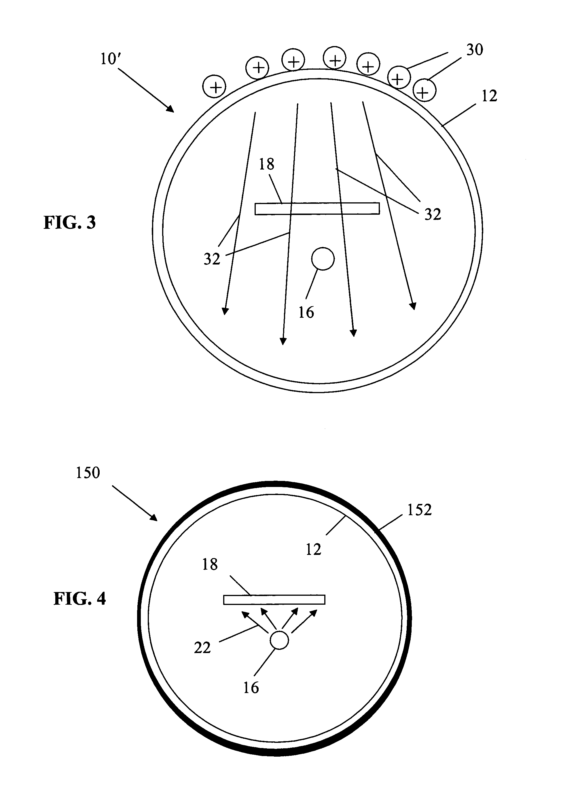
As will be further described, an electric field is easily overwhelmed by the presence of noise sources.
As a result, detection of small or distant fires is difficult at best and typically fraught with the problem of unacceptable false alarms.
However, when placed at above absolute zero temperatures and due to crystal structure imperfections, these cut-off wavelength values blur considerably.
As a result, the rather unpredictable response of GM tubes to solar UVB radiation around 280 nm becomes critical to maintaining an acceptable signal-to-noise (SNR).
Poisson or “shot” noise in the signal as well as cosmic ray background noise becomes problematic in the attempt to extract the fire signal from the background noise.
Since the background noise characteristic further worsens in sunlight conditions, this background noise characteristic of R2868 as supplied by the manufacturer is unacceptable in detecting the presence of wildfire and electrical arcs at long distances.
This time integration method is inadequate for use in the long distance detection of wildfires and flames because the photon count over time may be very low for a long period of time but increase exponentially over a short time period.
Since early detection is key in this application, the resetting of the photon count at the end of each integration period may lead to the loss of precious time in detection of far away but significant fire sources.
However, this feature proves difficult since conventional circuitry, even of low power, CMOS variety, may consume enough power to require unacceptably frequent battery replacement.

Method used


Image

  • Remote sensing and signaling of the presence of wildfire
  • Remote sensing and signaling of the presence of wildfire
  • Remote sensing and signaling of the presence of wildfire

Examples


Embodiment Construction

[0033]The following description is presented to enable one of ordinary skill in the art to make and use the invention and is provided in the context of a patent application and its requirements. Various modifications to the described embodiments will be readily apparent to those skilled in the art and the generic principles herein may be applied to other embodiments. Thus, the present invention is not intended to be limited to the embodiment shown but is to be accorded the widest scope consistent with the principles and features described herein.

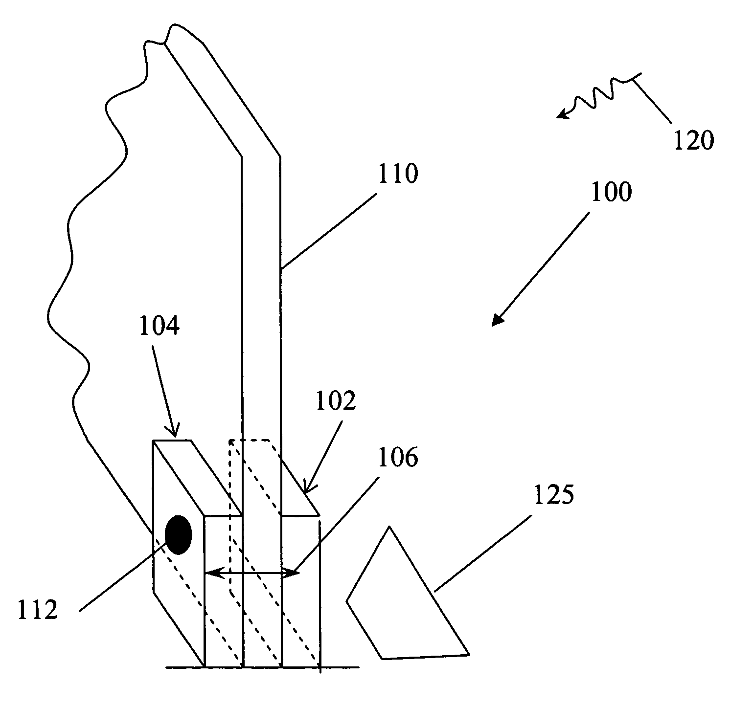
[0034]It would be desirable to obtain a compact system for wildfire detection which is suitable for use by a typical homeowner and is readily mountable by, for example, hook-and-loop attachment to the outside and / or inside of a window.

[0035]The present invention provides a way to increase the sensitivity of a photo-electric avalanche tube (GM tube) to the UVC photons associated with flames or electrical sparks, while simultaneously suppressi...


PUM


Abstract

Detecting a wildfire and an electrical arc, which are characterized by emission of ultraviolet (UV) radiation at a given wavelength, are described using a light sensor having a pulse output responsive to the given wavelength and generating an intermediate output responsive to the pulse output in a way which tracks a trend in the pulse output, irrespective of any increase in the relative number of pulses in the pulse output that is responsive to extraneous sources other than wildfire or electrical arc. The intermediate output is generated responsive to pulses occurring within an event window that continuously terminates at present time and extends backward therefrom by a selected time duration. An alarm signal is produced based on a predetermined characteristic of the intermediate output. Packaging of the sensor and alarm arrangement is described along with photo-detection tube optimization. Further, atmospheric transmission of the detected wavelength is described.

Description

BACKGROUND OF THE INVENTION[0001]The present invention relates generally to fire detection systems and, more specifically, to fire detection systems for sensing the presence of fire and / or precursors thereof which are located remotely therefrom.[0002]As more residences are built in forested parts of the country, the danger of wildfire becomes ever more ominous due to the number of lives and properties that are at risk. Particularly in dry or windy times and locations, a wildfire can double in size every few minutes. Without early detection, such a fire can quickly overwhelm any resources available to fight the fire. Early detection by a homeowner can in many cases ensure notification of the fire department while the fire is still small enough to be stopped or, if necessary, an emergency evacuation by the homeowner. However, no homeowner can be constantly on the lookout for wildfires, particularly at night. It is well known that wildfires may grow exponentially in dry weather, steep ...

Claims


Application Information

Patent Timeline
Patent Type & Authority Patents(United States)
IPC IPC(8): G08B17/12
CPCG08B17/12
Inventor SMITH, ROBERT J.
Owner SMITH ROBERT J
Learn More