Dynamic allocation of transmission bandwidth in a communication system

a communication system and transmission bandwidth technology, applied in the field of communication systems, can solve the problems of power consumption of the system, many users without service, and no reference to a communication system for telephony communications, and achieve the effect of flexible bandwidth provision

Inactive Publication Date: 2006-10-17
HTC CORP
View PDF44 Cites 52 Cited by
  • Summary
  • Abstract
  • Description
  • Claims
  • Application Information

AI Technical Summary

Benefits of technology

[0031]Another embodiment prevents untoward spectral effects in the multicarrier signal from variations in channel activity and from highly repetitive data patterns in the payload channels. Data is the payload channels can be scrambled with pseudorandom sequences, and different sequences can be applied to different channels in order to produce a more balanced multicarrier spectrum.
[0068]In another embodiment, a telecommunications system provides a method for using an upstream payload channel to inform the head end of errors that occur in downstream payload channels. The system, monitors a downstream transmission channel at a service unit for transmission errors. Further, the system generates a signal at the service unit that indicates transmission errors in the downstream payload channel. The system also transmits the signal to the head end on an associated upstream payload channel thus allowing the head end to monitor and respond to the performance of the service unit and associated payload channels.

Problems solved by technology

Although the above-mentioned networks describe various concepts for transmitting broad band video signals over various architectures, which may include hybrid optical fiber / coax architectures, none of these references describe a cost effective, flexible, communications system for telephony communications.
Several problems are inherent in such a communication system.
One such problem is the need to optimize the bandwidth used for transporting data so that the bandwidth used does not exceed the allotted bandwidth.
A second problem involves power consumption of the system.
Another problem arises from a fault in the system preventing communication between a head end and multiple remote units of a multi-point to point system.
For example, a cut transmission line from a head end to many remote units may leave many users without service.
Both internal and external interference can degrade the communication.
Internal interference exists between data signals being transported over the system.
That is, transported data signals over a common communication link may experience interference therebetween, decreasing the integrity of the data.
A telephony communication network is susceptible to “noise” generated by external sources, such as HAM radio.
Moreover, once the enhanced system is described, a number of practical problems in its physical realization are presented and overcome.
In addition to the speed and data-throughput requirements, power consumption is a major concern for many applications.
In some signal-processing applications, power is supplied by portable generation or storage equipment, such as batteries, where the ultimate power available is limited by many environment.
Ultimately, one key problem with any FFT processor is the amount of power consumed per transform.
As a consequence, reasonably large transforms required to process large arrays of data, result in large power consumption.
Heretofore, FFT processors generally fetched data values from their working storage in a serial manner, thus limiting the speed which could be obtained.
Further, current FFT processors generally were limited in speed by loading the working storage with input values, then processing the data in the working storage, then unloading the result values.

Method used


Image

  • Dynamic allocation of transmission bandwidth in a communication system
  • Dynamic allocation of transmission bandwidth in a communication system
  • Dynamic allocation of transmission bandwidth in a communication system

Examples


first embodiment

Operation of First Embodiment

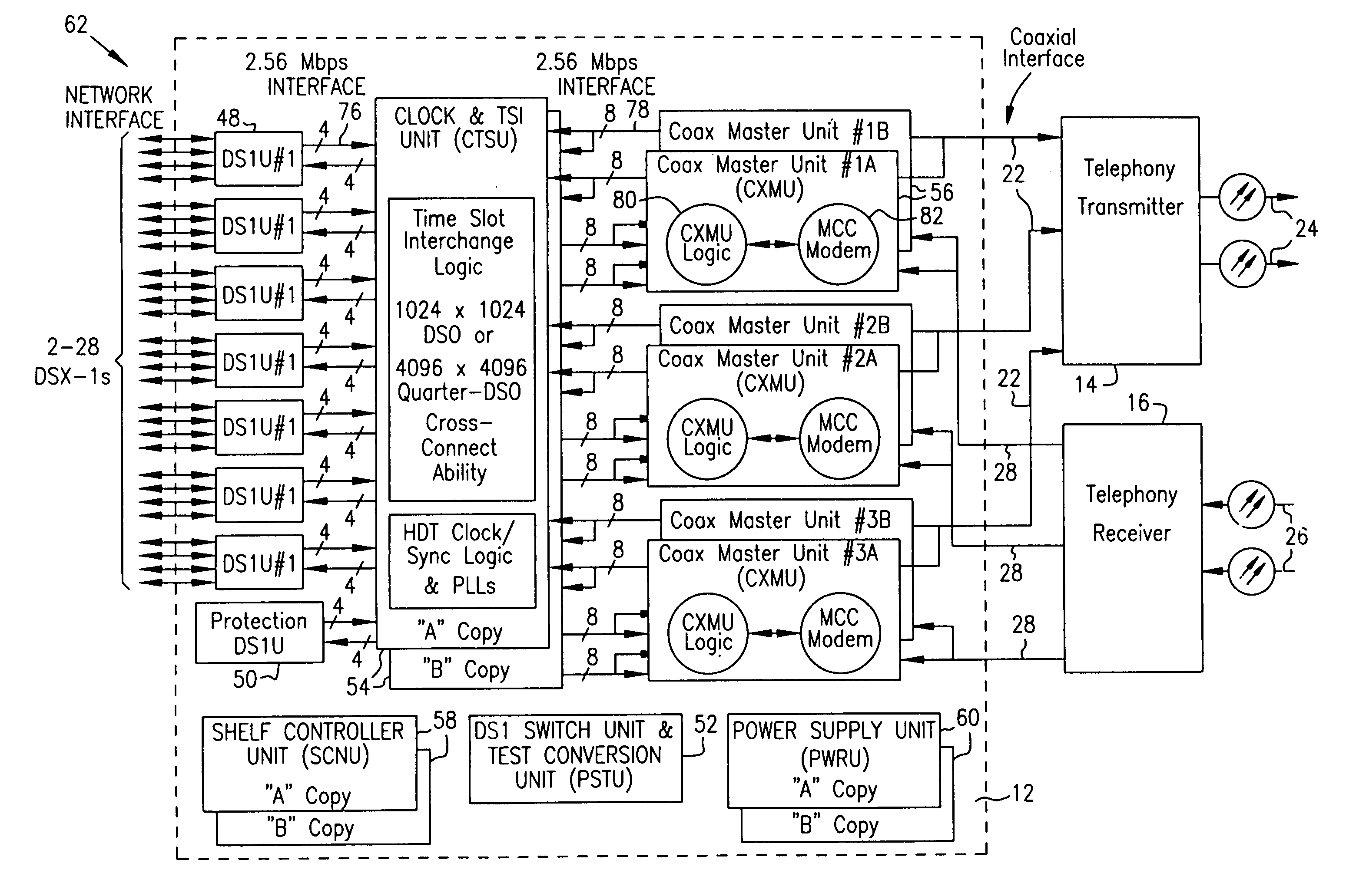
[0326]In the preferred embodiment, the 6 MHz frequency band for each MCC modem 82 of HDT 12 is allocated as shown in FIG. 13. Although the MCC modem 82 transmits and receives the entire 6 MHz band, the ISU modems 100 (FIG. 8) are optimized for the specific application for which they are designed and may terminate / generate fewer than the total number of carriers or tones allocated in the 6 MHz band. The upstream and downstream band allocations are preferably symmetric. The upstream 6 MHz bands from the MCC modems 82 lie in the 5–40 MHz spectrum and the downstream 6 MHz bands lie in the 725–760 MHz spectrum. One skilled in the art will recognize that if different transmission media are utilized for upstream and downstream transmission, the frequencies for transmission may be the same or overlap but still be non-interfering.

[0327]There are three regions in each 6 MHz frequency band to support specific operations, such as transport of telephony payload data,...

second embodiment

of Telephony Transport System

[0429]A second embodiment of an OFDM telephony transport system, referring to FIGS. 36–39 shall be described. The 6 MHz spectrum allocation is shown in FIG. 36. The 6 MHz bandwidth is divided into nine channel bands corresponding to the nine individual modems 226 (FIG. 37). It will be recognized by one skilled in the art that less modems could be used by combining identical operations. Each of the channel bands includes 32 channels modulated with a quadrature 32-ary format (32-QAM) having five bits per symbols. A single channel is allocated to supported transfer of operations and control data (IOC control data) for communition between an HDT 12 and ISUs 100. This channel uses BPSK modulation.

[0430]The transport architecture shall first be described with respect to downstream transmission and then with respect to upstream transmission. Referring to FIG. 37, the MCC modem 82 architecture of the HDT 12 will be described. In the downstream direction, serial ...

embodiment

ATM Embodiment

[0609]The system 500 of the prevent invention can also be configured to carry data from an Asynchronous Transport Mode (ATM) network. As shown in FIGS. 114 and 115, system 10 or 500 of the present invention is modified to include an ATM multiplexer / modulator 650 which can receive ATM data from an ATM network 652 and modulate it onto the HFC network. In one preferred embodiment, digital video data is delivered over ATM network 652, multiplexed and modulated using multiplexer / modulator 650 onto the HFC network in RF digital OFDM format on assigned data and / or telephony channels between the head end and a subscriber, as for example described above with respect to system 50 or 500. A digital set top box 654 receives the digital video, formatted for example in 4.0 Mbps MPEG or equivalent, and converts it to video for display on a television 656. A return path to the HDT 12 over a telephony or data channel allows for interactive digital video. A video server 658 and ATM swit...


PUM


Abstract

A head end is provided. The head end includes at least one modern for communicating with service units over a transmission bandwidth, the transmission bandwidth being divided into a number of subbands, each subband including a plurality of payload channels and at least one control channel and a control circuit, communicatively coupled with the at least one modem, that assigns each service unit to a subband such that the service units are substantially evenly distributed over the subbands.

Description

CROSS REFERENCE TO RELATED CASES[0001]This Application is a divisional application of U.S. Pat. 6,279,158 (application Ser. No. 09 / 397,443, filed Sep. 15, 1999), issued Aug. 21, 2001 which is a divisional of U.S. Pat. No. 6,334,219 (application Ser. No. 08 / 673,002, filed Jun. 28, 1996) issued Dec. 25, 2001 which is a continuation-in-part of U.S. application Ser. No. 08 / 650,408 filed May 20, 1996 (abandoned), Ser. No. 08 / 457,295 filed Jun. 1, 1995 (abandoned), Ser. No. 08 / 384,659 filed Feb. 6, 1995 (abandoned), and Ser. No. 08 / 457,317 filed Jun. 1, 1995 (abandoned). U.S. application Ser. No. 08 / 650,408 filed May 20, 1996 (abandoned), Ser. No. 08 / 457,295 filed Jun. 1, 1995 (abandoned), Ser. No. 08 / 384,659 filed Feb. 6, 1995 (abandoned), and Ser. No. 08 / 457,317 filed Jun. 1, 1995 (abandoned) are hereby incorporated herein by reference.[0002]This application is related to U.S. application Ser. No. 08 / 311,964 filed Sep. 26, 1994 (abandoned), Ser. No. 08 / 455,340 filed May 31, 1995 (abando...

Claims


Application Information

Patent Timeline
Patent Type & Authority Patents(United States)
IPC IPC(8): H04J4/00G06F17/14H04B10/272H04H20/69H04H20/76H04H20/77H04H20/78H04H20/79H04H20/80H04H60/86H04H60/96H04H60/97H04J3/14H04J14/02H04L1/00H04L1/24H04L5/02H04L5/14H04L12/10H04L12/12H04L12/24H04L12/26H04L12/28H04L12/44H04L25/03H04L27/00H04L27/26H04L27/34H04M7/00H04M9/02H04N7/173H04N7/22H04N21/222H04N21/2383H04N21/2385H04N21/24H04N21/438H04N21/61
CPCG06F17/14G06F17/142H03M13/356H04B10/272H04H20/69H04H20/78H04H20/79H04H20/80H04H60/11H04H60/86H04H60/96H04H60/97H04J3/14H04J14/0298H04K1/00H04K3/226H04K3/255H04L1/004H04L1/0045H04L1/0057H04L1/24H04L5/0037H04L5/0044H04L5/023H04L5/14H04L5/143H04L5/1484H04L12/10H04L12/12H04L12/2602H04L12/2801H04L12/44H04L25/03866H04L27/2601H04L27/2608H04L27/2614H04L27/2626H04L27/2628H04L27/2647H04L27/265H04L27/2652H04L27/2655H04L27/2657H04L27/34H04L41/0896H04L43/00H04L43/022H04L43/0823H04L43/0829H04M7/006H04N7/17309H04N7/22H04N21/2221H04N21/2383H04N21/2385H04N21/2402H04N21/4382H04N21/6118H04N21/6137H04N21/6168H04W24/00H04W24/08H03M13/1515H04H20/77H04L1/0071H04L5/0007H04L27/2662H04L41/0213H04L41/064H04L43/067H04L43/0811H04L43/0817H04L43/0847H04L43/0852H04L43/0858H04L43/0864H04L43/0882H04L43/16H04L2001/0093H04L2027/0036H04L2027/0057H04L2027/0067H04M9/027Y02B60/34Y02B60/35H04L27/2634H04L27/2631Y02D30/50H04L27/2654H04L27/26524
Inventor GEILE, MICHAEL J.ANDERSON, BRIAN D.BREDE, JEFFREYKIRSCHT, ROBERT J.FORT, MICHAEL J.ELPERS, MARK D.
Owner HTC CORP
Why Eureka
Try Eureka