Millimeter wave-radar and method for manufacturing the same

Inactive Publication Date: 2006-10-24
HITACHI LTD
View PDF9 Cites 45 Cited by
  • Summary
  • Abstract
  • Description
  • Claims
  • Application Information

AI Technical Summary

Benefits of technology

[0009]With this construction, a mutual engagement between the radio wave absorbing layer that blocks the transmission of radio waves and the material of the radome or the radar cover is facilitated. This construction also allows the performance of the radio wave absorbing layer to be adjusted according to its position with respect to the surface of the transmission/reception antenna. As a result, the layer can offer a maximum performance for radio wave absorption with a minimum required thickness of layer, thereby preventing sidelobes of radiated electromagnetic waves from being reflected by objects surrounding a radar fixing portion.
[0010]The radio wave absorbing layer is a layer with a greater dielectric loss than that of the material of the radome or radar cover, or a magnetic loss layer. Among preferred materials with a high dielectric loss are carbon materials (carbon nanotube, carbon microcoil, shungite carbon, carbon black, expanded graphite, carbon fiber, etc.). Examples of preferred magnetic loss layer include hexagonal ferrite and metals. It is also preferred that the radio wave absorbing layer be formed into a mesh of less than ¼ of wavelength so that its own weight can be reduced while maintaining the performance for radio wave absorption.
[0011]It is preferred that the dielectric constant of the main materials for the radome and the radar cover, which affects the radio wave transmission characteristic, be adjusted in such a manner that the dielectric constant of a portion of the radome and the radar cover corresponding to the side of the

Problems solved by technology

Conventional millimeter wave-radars have a problem that sidelobes of radiated electromagnetic waves are reflected by objects surrounding a radar fixing portion, resulting in unwanted objects also being detected in addition to targeted objects.
In the conventional technique described above, however, since the metal plate or radio wave absorber mounted around the transmission/reception antennas are separated from a radome enclosing the antennas, t

Method used


Image

  • Millimeter wave-radar and method for manufacturing the same
  • Millimeter wave-radar and method for manufacturing the same
  • Millimeter wave-radar and method for manufacturing the same

Examples


Embodiment Construction

[0025]An embodiment of this invention will be described with referring to the accompanying drawings.

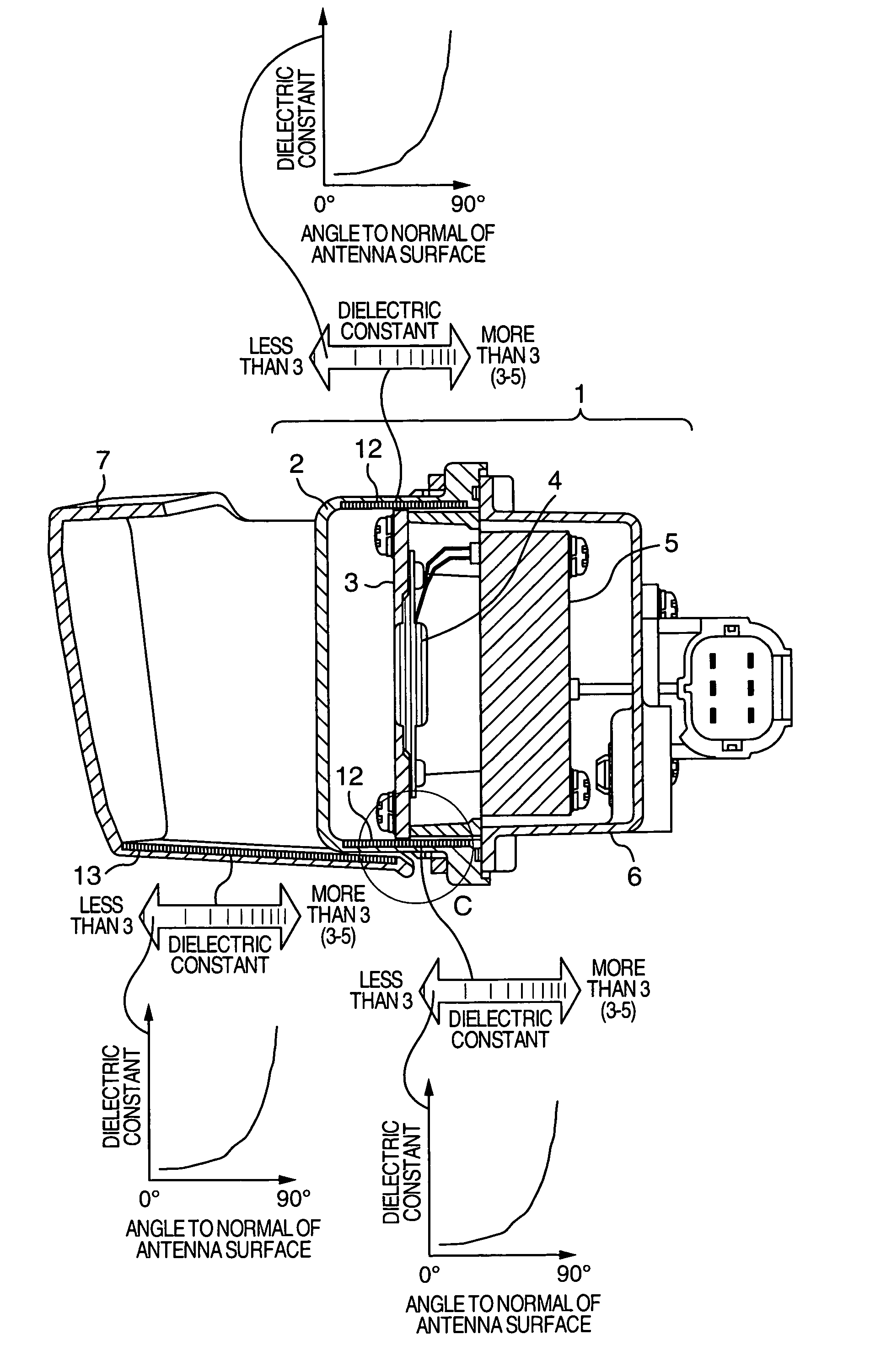
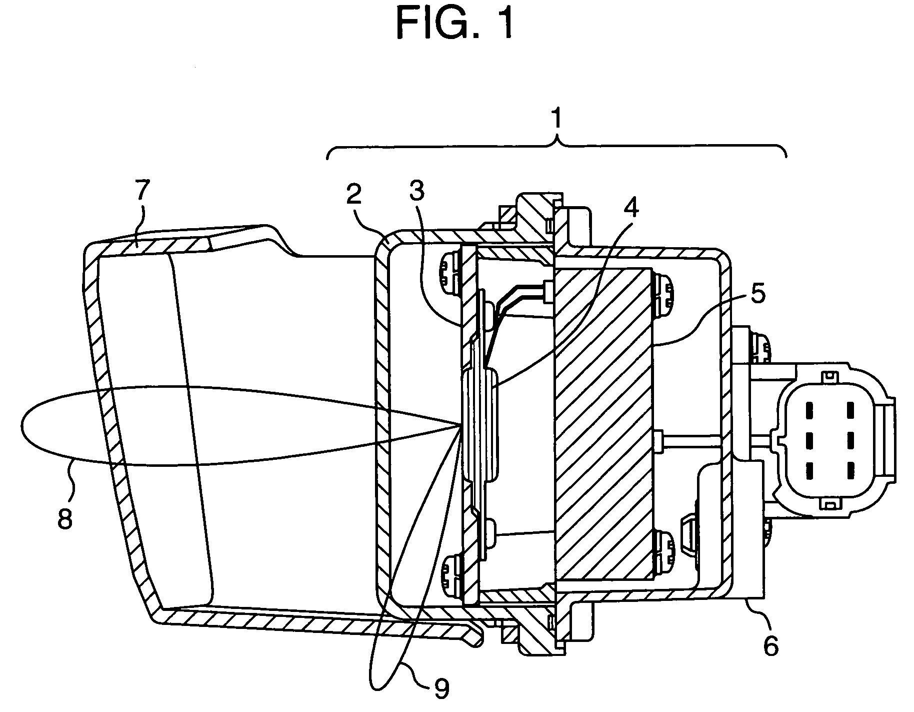
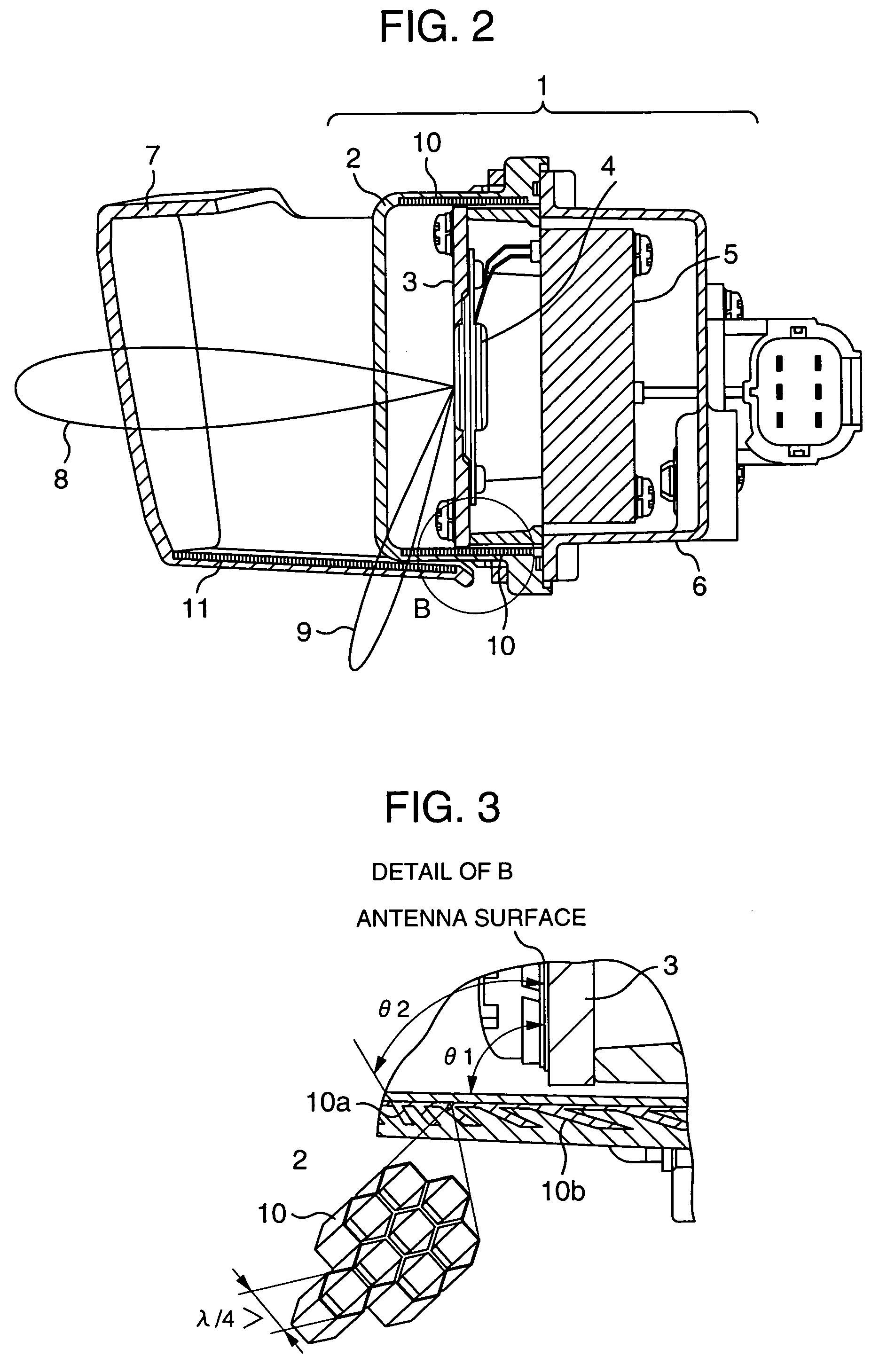
[0026]FIG. 11 shows a front view of a millimeter-wave radar and FIG. 1 is a cross-sectional view of the millimeter-wave radar taken along the line A—A of FIG. 11. The millimeter-wave radar of FIG. 1 comprises a radome 2, an antenna base 3 incorporating transmission and reception antennas, a control circuit 5, an RF module 4, and a housing 6 fixing the antenna base 3 and accommodating the control circuit 5 and the RF module 4. In front of the antenna base 3 is mounted the radome 2 that covers the entire surface of the antenna base and protects it against bouncing pebbles and rain. Depending on circumstances a radar cover 7 may be installed in front of the radome 2 to enclose it. Further, only the radar cover 7 may be used without the radome 2. It is also possible to use a windshield of the car as a radar cover.

[0027]Reference numbers 8 and 9 in FIG. 1 conceptually represent a main beam...


PUM


Abstract

A millimeter-wave radar has a radome or radar cover including a layer, the dielectric constant of which is a greater than that of the other portion without the layer, or including a magnetic loss layer in an appropriate position with respect to the antenna. The dielectric constant of the radome or radar cover can be made higher in a portion corresponding to the side of the antenna than in a portion corresponding to the front of the antenna.

Description

BACKGROUND OF THE INVENTION[0001]The present invention relates to a millimeter wave-radar mounted on automobiles and a method of manufacturing the same.[0002]A millimeter wave-radar for automatic guidance and collision avoidance of a vehicle radiates an electromagnetic wave of a millimeter band in a desired direction and receives a reflected wave from objects in front of the radar to detect possible obstacles.[0003]Conventional millimeter wave-radars have a problem that sidelobes of radiated electromagnetic waves are reflected by objects surrounding a radar fixing portion, resulting in unwanted objects also being detected in addition to targeted objects. A conventional countermeasure to deal with this problem involves installing a metal plate or electromagnetic wave absorber on a plane of and around the transmission / reception antenna in an antenna unit so that it protrudes from the antenna surface, in order to reduce sidelobes, as shown in, for example, JP-A-10-126146.[0004]In the c...

Claims


Application Information

Patent Timeline
IPC IPC(8): G01S13/93G01S7/03G01S13/931H01Q1/42H01Q17/00
CPCG01S7/03G01S7/2813G01S13/931H01Q1/42H01Q17/001G01S2013/9389G01S2013/93275
Inventor SUZUKI, MITSUSHIGETAKANO, KAZUAKI
Owner HITACHI LTD
Why Eureka
Try Eureka