Oblique plate compensators for projection display systems

Active Publication Date: 2006-10-24
REAID INC
View PDF7 Cites 12 Cited by
  • Summary
  • Abstract
  • Description
  • Claims
  • Application Information

AI Technical Summary

Benefits of technology

[0004]The present application describes compensators and method of making compensators for a compensation scheme for liquid crystal display projection systems. According to an embodiment, the compensation scheme improves azimuth-averaged contrast and is substantially unconstrained by specific azimuth-dependent contrast requirements that are common in

Problems solved by technology

The less expensive and lower contrast projections systems use a single retarder film per panel to provide compensation, while the more expensive and higher contrast projection systems use a retarder fi

Method used


Image

  • Oblique plate compensators for projection display systems
  • Oblique plate compensators for projection display systems
  • Oblique plate compensators for projection display systems

Examples


Embodiment Construction

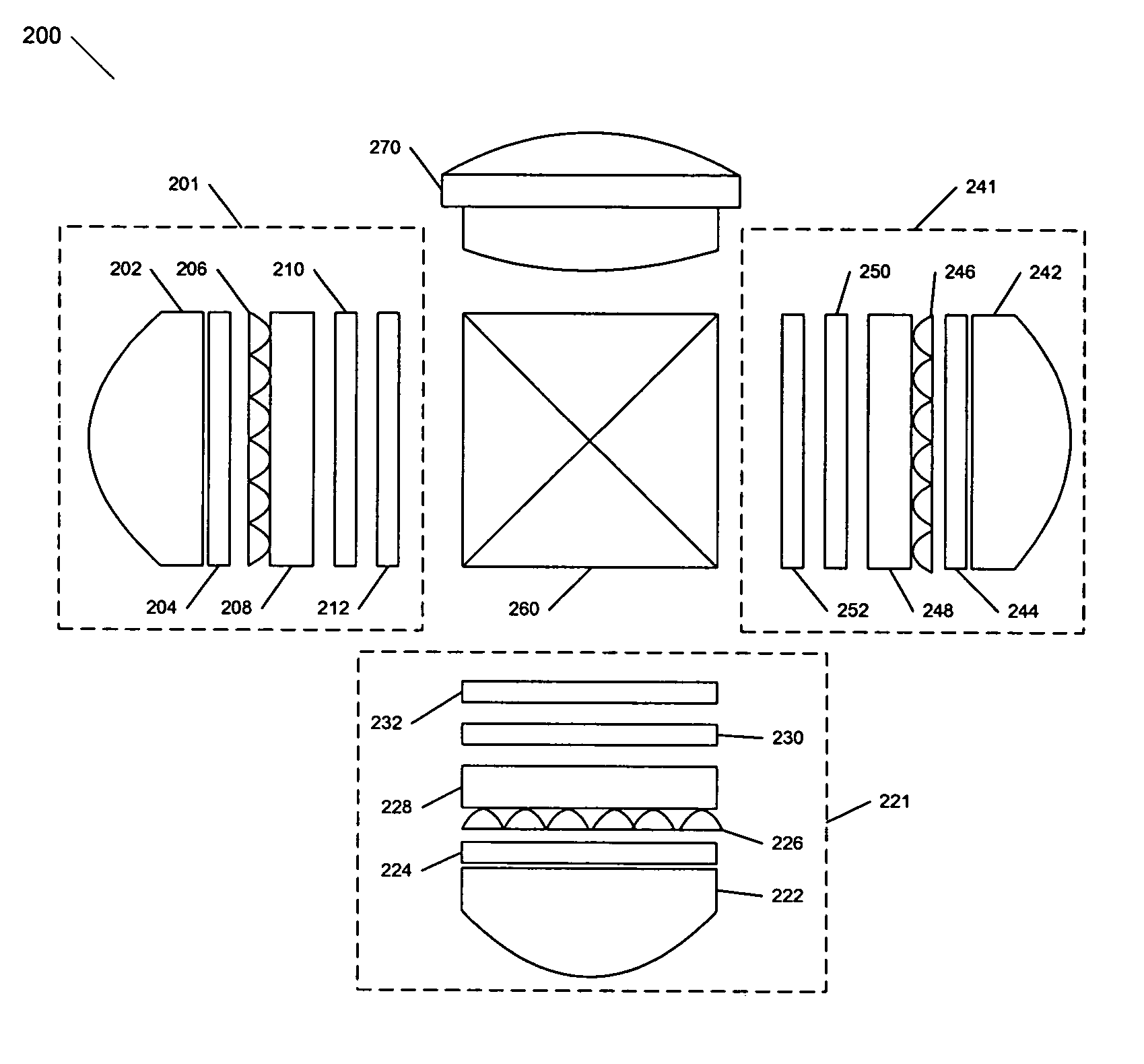
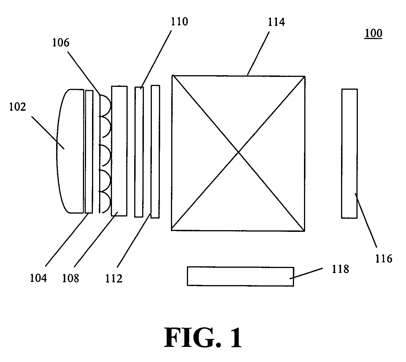
[0019]The desired sequential contrast of projection systems has and continues to increase, owing in part to the high performance of digital light processing based projection systems. Liquid crystal panels, such as high temperature polycrystalline silicon (HTPS) twisted nematic liquid crystal displays, are transmissive in nature and have a small diagonal size (<1.2″ or <3.1 cm). These panels use a twisted nematic liquid crystal alignment, operating in a normally white mode, with the polarized light introduced parallel to the rub direction, it is e-mode. However the compensation scheme works for both e and o mode. For e-mode, the rub direction of LC is parallel to the direction of polarizer while in o-mode, the rub direction of LC is perpendicular to the direction of polarizer. The projection systems operate at typical f-numbers of 2.5 at the input side so as to efficiently utilize lamp emission. When the projection systems include micro-lens arrays, image light is transmitted at much...


PUM


Abstract

Projection systems having o-plate compensation elements are described. The compensation elements may be negative, positive or biaxial anisotropic element and may have a homogeneous tilt or a splayed tilt. The compensation elements may be formed from a polymer liquid crystal. The compensation elements are designed to maximize azimuth-averaged contrast. The compensation elements may be placed on the same side of a liquid crystal panel when a micro-lens array is used to improve the ease of manufacture.

Description

PRIORITY CLAIM AND RELATED APPLICATION[0001]The present application claims priority from U.S. Provisional Application entitled “Compensators and Methods,” Ser. No. 60 / 422,437 filed Oct. 30, 2002, having Jianmin Chen, Michael G. Robinson, and Gary D. Sharp as inventors, and having as assignee ColorLink, Inc., the assignee of the present application. This provisional application is incorporated herein by reference in its entirety for all purposes.FIELD OF THE INVENTION[0002]The present invention relates generally to compensators, and more particularly, to oblique-plate compensators for liquid crystal projection display systems.BACKGROUND[0003]Projection systems have contrast needs that are continually increasing while the projection system marketplace desires more cost effective components and system configurations. These projection systems liquid crystal panels for modulating red, green, and blue light (i.e., the primary colors) or other light spectra, wherein the liquid crystal pane...

Claims


Application Information

Patent Timeline
IPC IPC(8): G02F1/1335G02B5/30G02F1/13363H04N5/74H04N9/31
CPCG02B5/3083G02F1/133632H04N9/3105H04N9/315H04N9/3197G02F2413/08H04N5/7441
Inventor CHEN, JIANMINROBINSON, MICHAEL G.SHARP, GARY D.
Owner REAID INC
Why Eureka
Try Eureka