
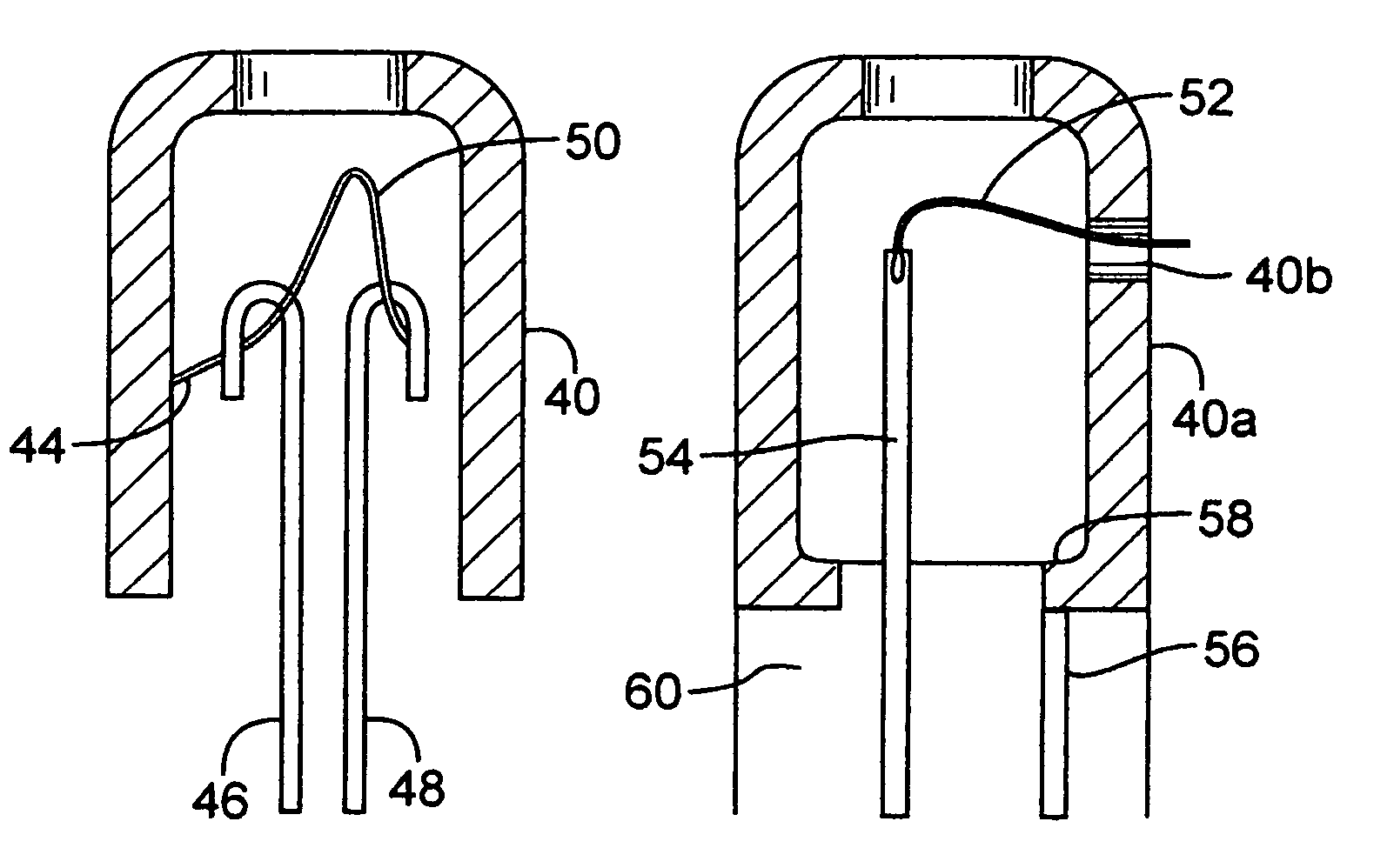
Extractor cup on a miniature x-ray tube

a miniature x-ray tube and extractor cup technology, applied in the direction of x-ray tubes, discharge tubes/lamp details, discharge tube main electrodes, etc., to achieve the effect of high resistan

Active Publication Date: 2006-10-31
NUCLETRON OPERATIONS +1
View PDF4 Cites 34 Cited by
  • Summary
  • Abstract
  • Description
  • Claims
  • Application Information

AI Technical Summary

Benefits of technology

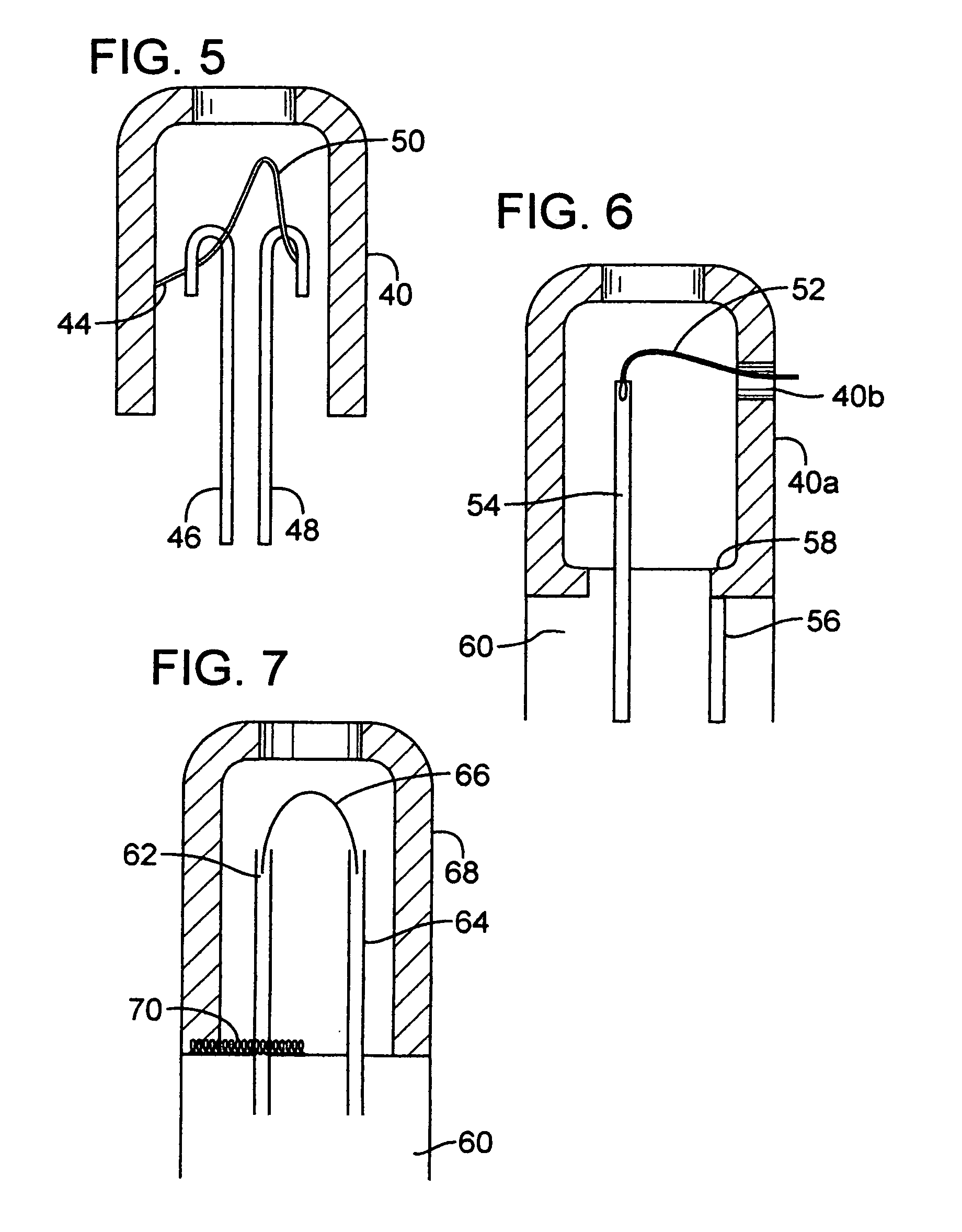
[0007]In a variation of the above, the cathode filament is pre-coated with a semiconductor material that will flash off or evaporate when heated. The shield is not included on either post, and the semiconductor material is evaporated onto the base along both posts and onto the extractor cup. The semiconductor material has a sufficiently high resistance as not to interfere with the low voltage circuit of the cathode filament so that current flow to heat the cathode is largely unaffected. This method also has the advantage of draining extraneous charge buildup from the extractor cup due to electrons striking the extractor.

Problems solved by technology

However, the connection of an extractor cup to high voltage, in a rugged, reliable and feasibly manufacturable manner, presents something of a challenge.
There are problems of reliably connecting a conductor to one end of a cathode filament or a wire lead to the cathode; it is not feasible simply to extend a conductor wire through the tube wall to the exterior, because of sealing problems and because of the requirement to isolate this HV from the tube exterior which is at ground potential; and in miniature size, which may be down to about 1 mm in tube diameter, the options are limited in making secure high voltage connections in proper alignment, to withstand high temperature, without causing the tube to fail ultimately through arcing and while still obtaining a rugged and reliable connection of the extractor cup to a base of the cathode and secure connection of the cathode itself to the base.

Method used


Image

  • Extractor cup on a miniature x-ray tube
  • Extractor cup on a miniature x-ray tube
  • Extractor cup on a miniature x-ray tube

Examples


Embodiment Construction

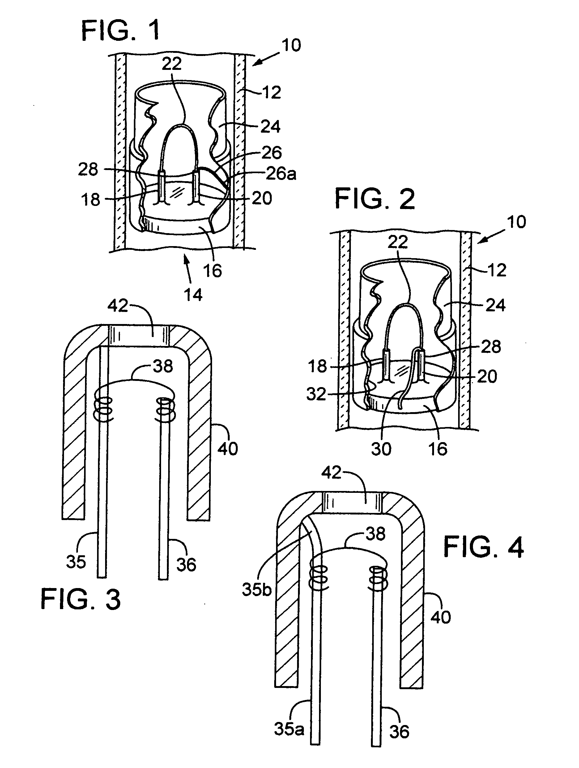
[0034]FIG. 1 shows a portion of a miniature x-ray tube 10, including a tube envelope 12 and a cathode assembly 14. Within the cathode assembly are a base 16, typically a glass preform, a pair of cathode filament supports posts or pins 18 and 20, a cathode filament 22, and an extractor cup 24. The filament support posts or pins 18 and 20 preferably extend up through openings in the base 16, being connected below the base to conductors which run through a flexible cable which may be part of a catheter. These posts, and the cathode filament 22, are in a low voltage cathode heater circuit, and high voltage potential is also supplied to the entire cathode so that electrons from the cathode will flow toward the anode (not shown) at the other end of the x-ray tube 10. Thus the two cathode posts or pins 18 and 20 are both at high potential, but different by the small amount of the low voltage circuit.

[0035]The extractor cup 24 should be at similar high voltage potential to the cathode filam...


PUM


Abstract

Methods for connecting electrical potential to an extractor cup at the cathode of a miniature x-ray tube are disclosed. The various connection schemes are designed to form a rugged and conveniently manufacturable connection between the metal extractor cup and one side of the cathode filament, so that the extractor cup shapes the path of electrons as desired en route to the anode of the tube. Some of the disclosed connections involve evaporation of conductive metal or other materials off the filament when the filament is first activated. Others involve applying a paste or paint conductive precursor directly to a base to connect a post and the extractor, the paste being heat-cured after the completion of assembly. Others involve a fine wire or spring strip from one filament post to the walls of the extractor cup. Other schemes include welded or brazed wires or foil, crimping, pinching, swaging and other connections, all made inside the tube enclosure.

Description

BACKGROUND OF THE INVENTION[0001]This invention concerns construction of miniature x-ray tubes. In particular the invention is directed at an efficient and rugged connection of a high voltage cathode filament lead to an extractor cup which helps shape the path of electrons from the cathode in such an x-ray tube.[0002]Miniature x-ray tubes, generally of the size and configuration contemplated in this invention, are shown in Xoft Microtube U.S. Pat. No. 6,319,188, and also in U.S. Pat. Nos. 5,854,822 and 5,621,780. Also, Xoft Microtube pending application Ser. No. 10 / 397,498 describes a cathode assembly with a cathode manufactured by MEMS technology and discloses a means of forming an extractor cup and electrically connecting the extractor cup to high voltage.[0003]As is known, an extractor cup is usually needed to help focus and direct the stream of electrons leaving a cathode en route to the anode in an x-ray tube, and the need for focusing this electron beam typically becomes more ...

Claims


Application Information

Patent Timeline
Patent Type & Authority Patents(United States)
IPC IPC(8): H01J35/32H01J35/06H01J35/14
CPCH01J35/06H01J35/14H01J35/147H01J35/066
Inventor LOVOI, PAUL A.VATAHOV, PETRE H.DOZIER, EARL E.SMITH, PETER C.REED, LEONARDNEIMEYER, ROBERT G.
Owner NUCLETRON OPERATIONS
Learn More