Method of locating object using phase differences among multiple frequency beacons transmitted from spaced apart transmitter sites

a technology of multiple frequency beacons and objects, applied in the field of communication, can solve the problems of gps system suffering when the receiver is subject to significant obstruction, gps location and tracking is not an all inclusive technique, etc., and achieves the effects of improving performance, improving sensitivity, and low signal-to-noise ratio

Inactive Publication Date: 2006-11-07
HARRIS CORP
View PDF5 Cites 33 Cited by
  • Summary
  • Abstract
  • Description
  • Claims
  • Application Information

AI Technical Summary

Benefits of technology

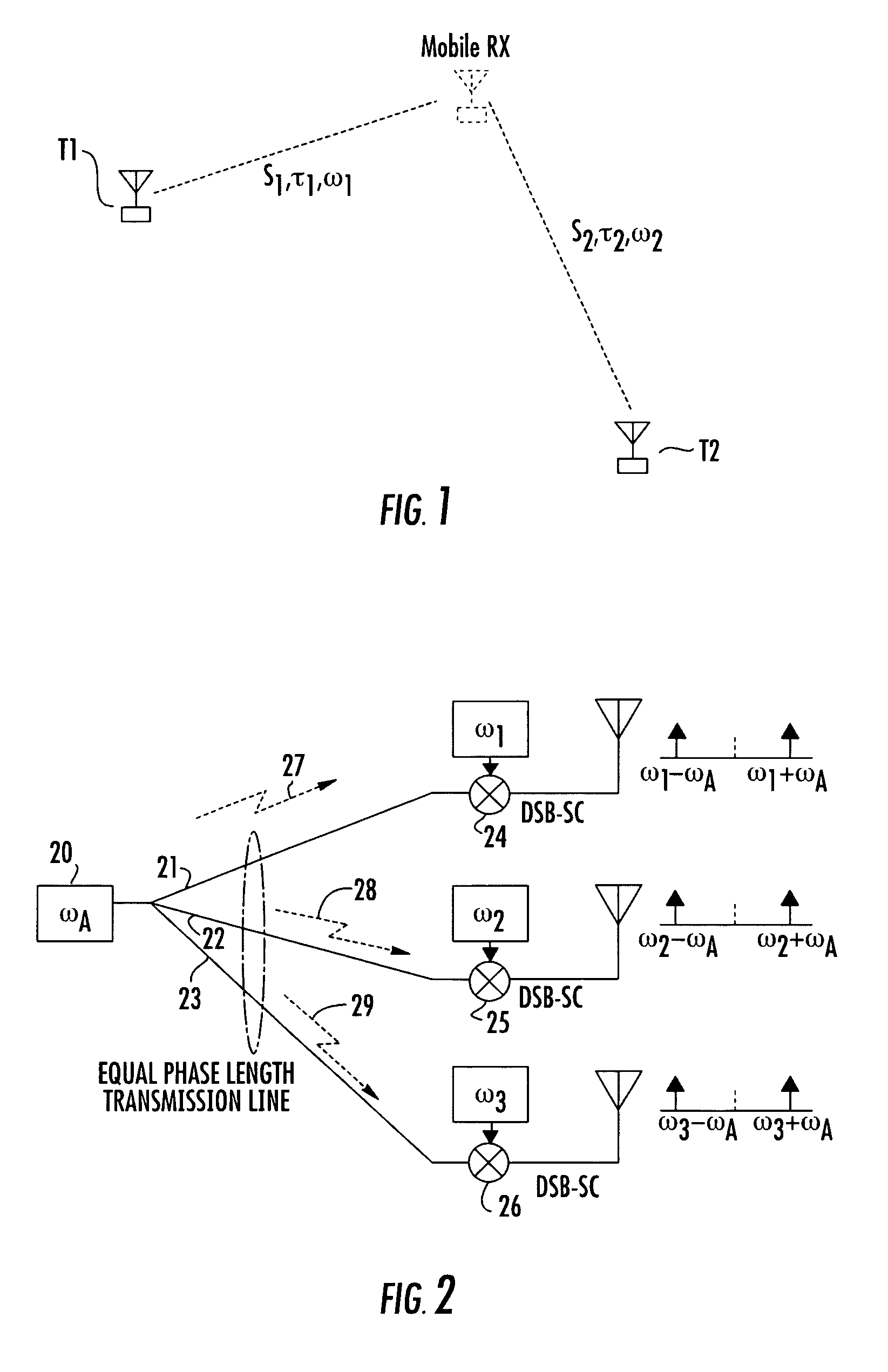
[0015]This equation reveals that the key frequency parameter is the frequency difference Δω rather than the two frequencies themselves. This implies that the operating frequency is not important—only the frequency difference between the two tones. It may be noted that the frequency difference Δω may be made arbitrarily as small or as large as desired. Making the frequency difference Δω small serves to avoid phase ambiguity (phase exceeding 180 degrees) over a long distance. For a frequency difference Δω of 1 KHz there will be no phase ambiguity for a distance up to a 150 km. Further, making the frequency difference Δω large improves the sensitivity of the phase detection and hence improves performance at a low signal-to-noise ratio (SNR). For example, for a frequency difference Δω of 1 MHz, a distance of 100 meters results in 120 degrees of phase shift (as opposed to 0.12 degrees of phase difference for a frequency difference Δω of 1 KHz over the same distance).
[0016]Determining the optimal value of Δω is not trivial, since a large value has significant implications for hardware implementation (i.e. the hardware starts to become relatively wideband which makes its implementation more difficult along with an increased chance of interference overload). For a relatively small value of Δω, building-induced phase shifts basically affect both tones equally and can be canceled out, it being assumed that the two signals have arrived via different paths. Namely, this technique is less susceptible to building construction-induced phase shifts—resulting in better ranging accuracy (again assuming that the frequency difference Δω is not excessive).

Problems solved by technology

Unfortunately, GPS location and tracking is not an all inclusive technique, as it generally requires that the GPS receiver be located outdoors, where there is a substantially unobstructed path between the GPS receiver and the GPS satellite network.
GPS systems suffer when the receiver is subject to significant obstruction, such as in the interior of a building, particularly the lower floors or an underground location (e.g., basement or parking garage).

Method used


Image

  • Method of locating object using phase differences among multiple frequency beacons transmitted from spaced apart transmitter sites
  • Method of locating object using phase differences among multiple frequency beacons transmitted from spaced apart transmitter sites
  • Method of locating object using phase differences among multiple frequency beacons transmitted from spaced apart transmitter sites

Examples


Embodiment Construction

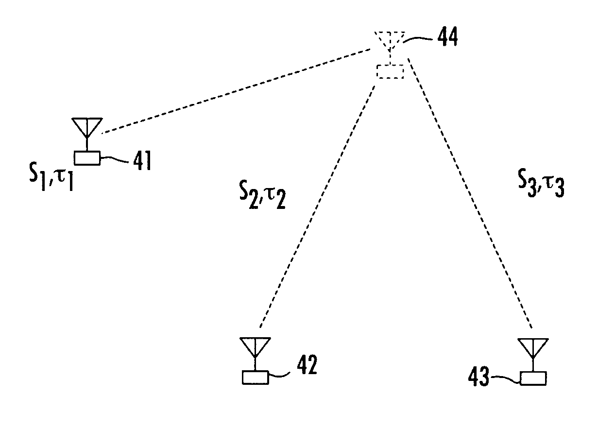
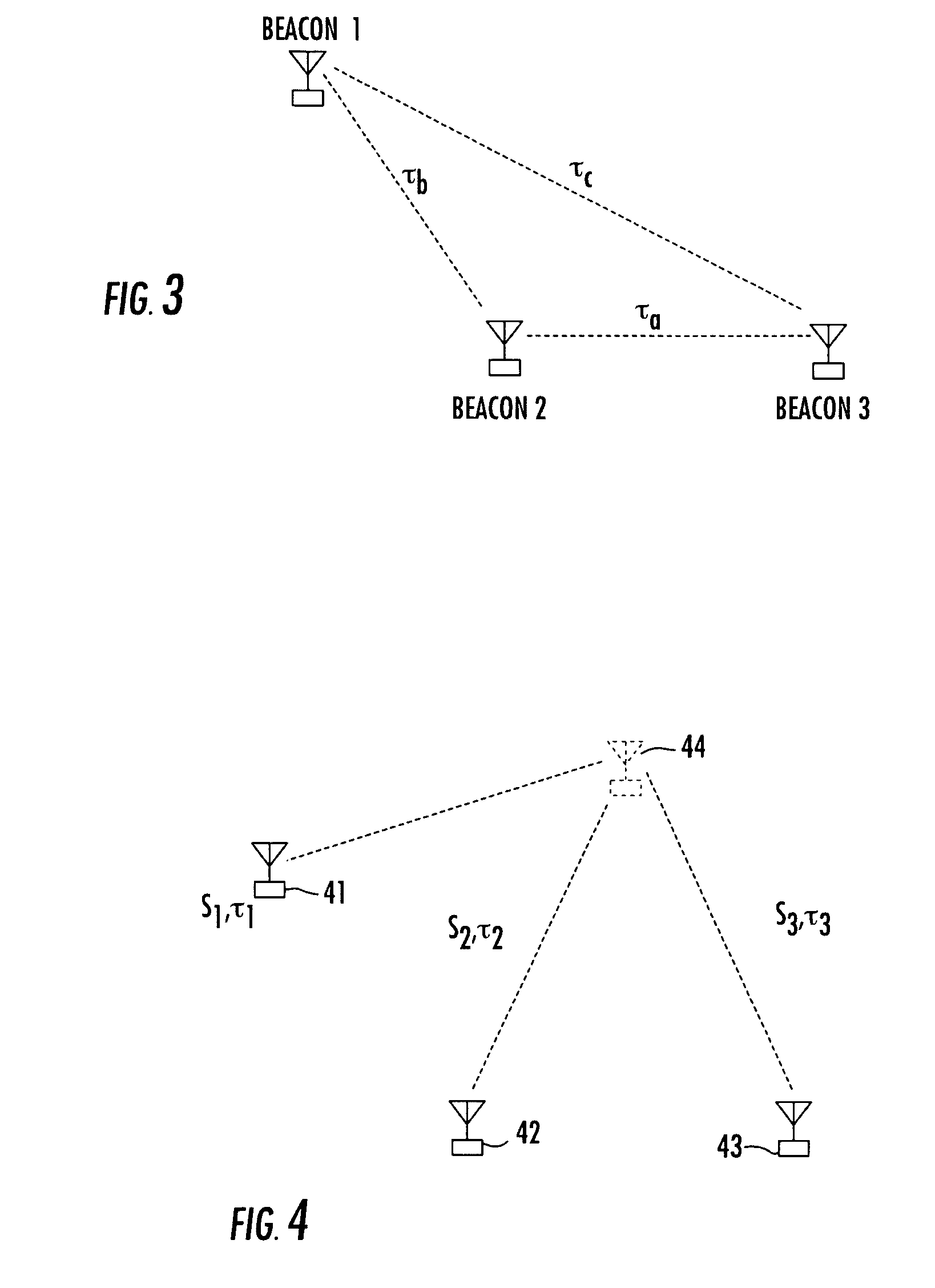
[0076]Before detailing the architecture and methodology of the multi-frequency beacon-based object location system in accordance with the present invention, it should be observed that the invention resides primarily in a prescribed novel arrangement of conventional communication circuits and components, and supervisory control software therefor that employs the phase and time difference algorithms of the invention. Consequently, the configurations of such circuits and components and the manner in which they may be distributed relative to an object whose location is to be determined have, for the most part, been shown in the drawings by readily understandable block diagrams, which show only those specific aspects that are pertinent to the present invention, so as not to obscure the disclosure with details which will be readily apparent to those skilled in the art having the benefit of the description herein. Thus, the system / network and subsystem (e.g., beacon transmitter) block diag...


PUM


Abstract

A technique for geolocating (mobile) objects within an environment where other locating systems, such as GPS-based systems, may not be expected to operate successfully, uses at least three transmitter sites whose geolocations are fixed and known, and which transmit dual frequency beacons that are readily received by a mobile receiver within the environment of interest. The object's receiver processes the three sets of received signals by measuring the phase differences among respective pairs of the beacons, and then processes these phase differences to perform time difference of arrival-based or time of arrival-based distance information to locate the object relative to the beacons sites. Phase errors or offsets are readily calibrated out, to realize geolocation information at the mobile receiver.

Description

FIELD OF THE INVENTION[0001]The present invention relates in general to communication systems and subsystems thereof, and is particularly directed to a new and improved technique for geolocating an object by measuring the phase differences of a plurality (e.g., three) multi-frequency beacons that are transmitted from an associated plurality of transmitter sites spaced apart from each other and from the object.BACKGROUND OF THE INVENTION[0002]The desire to locate and / or track an object, such as a vehicle or person, is a major objective of a variety of enterprises, such as but not limited to transportation, military and fire and rescue institutions. To this end, the use of the global positioning satellite (GPS) network has and continues to enjoy widespread use throughout the world. Unfortunately, GPS location and tracking is not an all inclusive technique, as it generally requires that the GPS receiver be located outdoors, where there is a substantially unobstructed path between the G...

Claims


Application Information

Patent Timeline
Patent Type & Authority Patents(United States)
IPC IPC(8): G01S5/06
CPCG01C21/206G01S5/06
Inventor ROBERTS, RICHARD D.
Owner HARRIS CORP
Why Eureka
Try Eureka