Multi-state spray cooling system

a spray cooling and multi-state technology, applied in the direction of domestic cooling apparatus, lighting and heating apparatus, and semiconductor/solid-state device details, etc., can solve the problems of increasing power dissipation requirements, increasing the total power dissipation level needed by computer systems, and increasing the heat generated by devices, so as to achieve efficient operation

Active Publication Date: 2006-11-14
SK HYNIX INC
View PDF14 Cites 38 Cited by
  • Summary
  • Abstract
  • Description
  • Claims
  • Application Information

AI Technical Summary

Benefits of technology

[0017]In various preferred embodiments, the present invention solves some or all of the needs mentioned above by providing a package-level cooling system that efficiently operates to provide accurate cooling to a component over a significant life span.

Problems solved by technology

With the advent of semiconductor devices having increasingly large component densities, the removal of heat generated by the devices has become an increasingly challenging technical issue.
Furthermore, typical processor boards can, in some instances, include multiple CPU modules, application-specific integrated circuits (ICs), and static random access memory (SRAM), as well as a dc-dc converter, all of which have increasing power dissipation requirements, thereby increasing the total power dissipation level needed by computer systems.
However, heat sinks are typically characterized by a mechanical interface to their cooled devices, which commonly leads to interference in the heat flow, and can lead to very high thermal resistance.
The mechanical interface can also lead to uneven cooling.
This is further complicated by the non-uniform power distribution on many chips, which often results when different components are integrated onto a single chip.
The use of these boiling / vaporizing methods is limited to a maximum power density, the critical heat flux (CHF).
However, these types of nozzles are limited in their ability to control the rate at which they spray.
Therefore, they can cause “pooling” (i.e., a buildup of liquid on the cooled device due to excessive spray rates).
Thus, the cooling system is a sensitive and potentially expensive device that can be a challenge to control.
While these types of nozzles typically provide superior control over the spray flow rate, it is possible that they might experience flow difficulties relating to their incremental spray mechanisms.
A number of factors affect the performance of spray cooling, thus affecting the heat transfer coefficient h and / or the CHF.
However, at a critical mass flow rate, the advantages of increased mass flow are diminished due to pooling and / or due to a transition to single phase heat transfer.
While spray cooling can provide excellent heat flux, spray cooling systems may have their difficulties.
Among these difficulties is the fact that spray cooling heads are finely tuned devices that can degenerate over a period of extensive use.
As a result, spray cooling systems might not have the life span that would otherwise be desired from a cooling system.
Also, the power requirements of spray cooling systems may be excessive when used to cool components that only occasionally need the high-heat-flux capabilities of spray cooling.

Method used


Image

  • Multi-state spray cooling system
  • Multi-state spray cooling system
  • Multi-state spray cooling system

Examples


Embodiment Construction

[0023]The invention summarized above and defined by the enumerated claims may be better understood by referring to the following detailed description, which should be read in conjunction with the accompanying drawings. This detailed description of particular preferred embodiments of the invention, set out below to enable one to build and use particular implementations of the invention, is not intended to limit the enumerated claims, but rather it is intended to provide particular examples thereof.

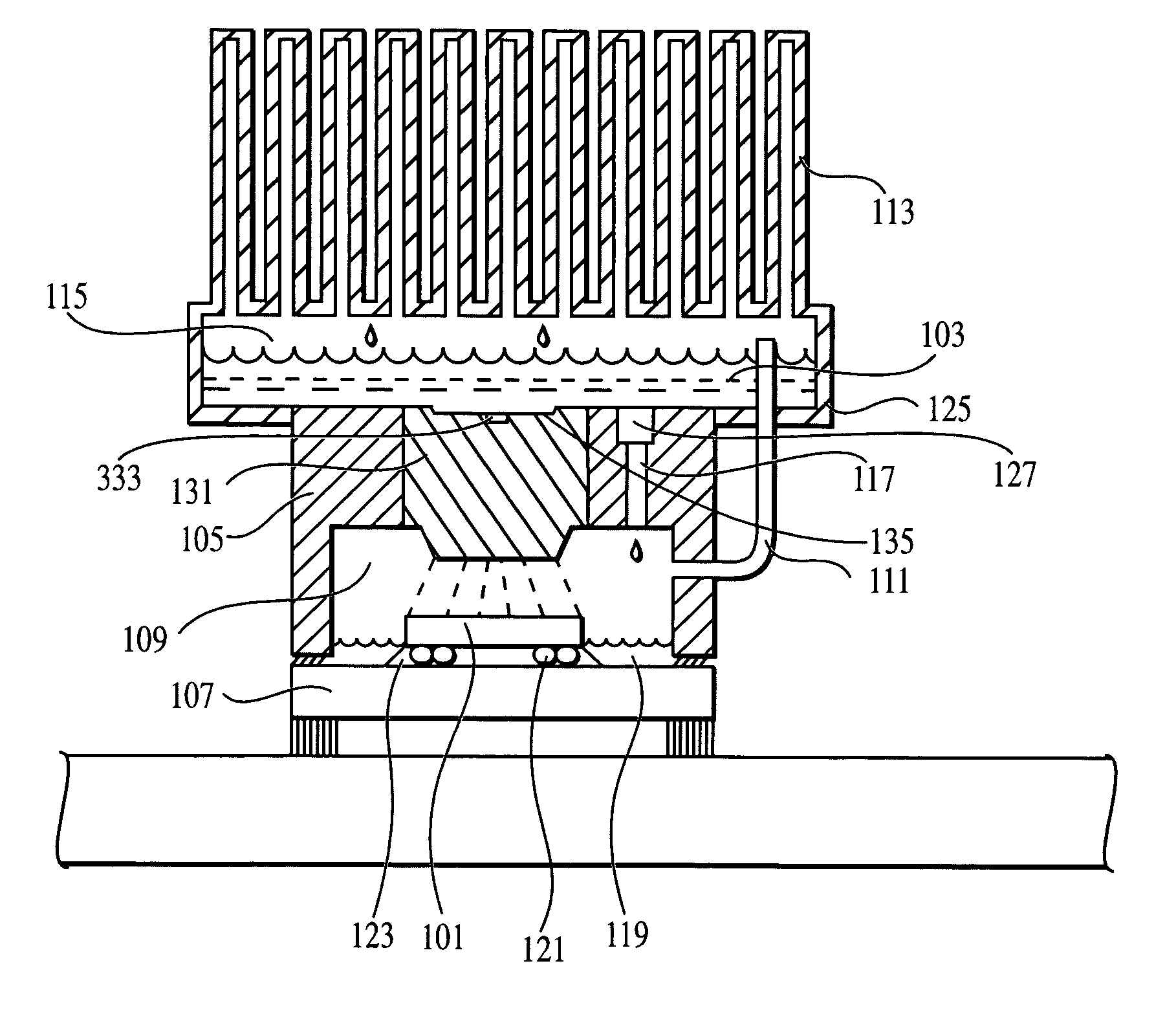
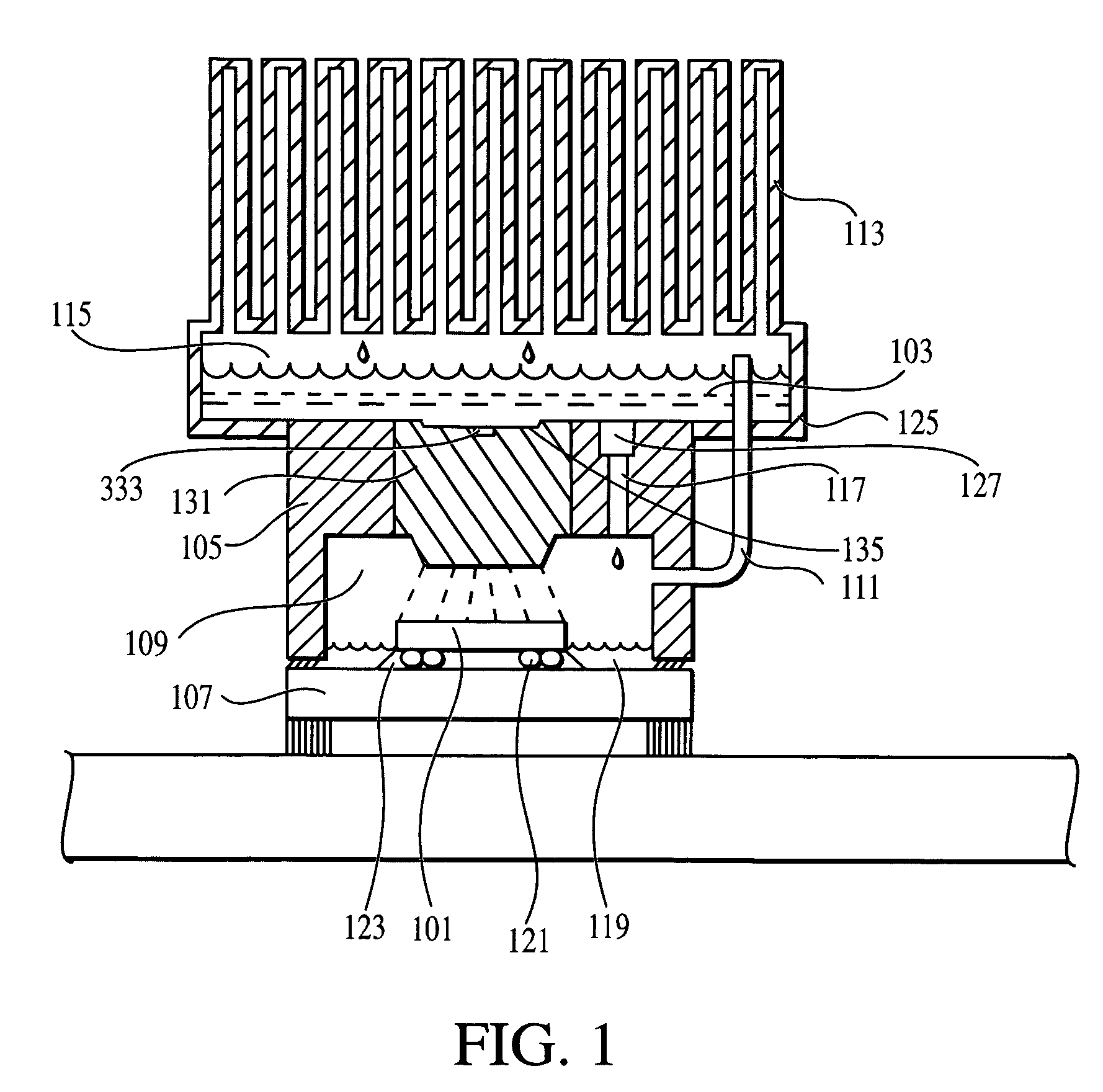
[0024]Evaporative spray cooling promises to be a technology that can deliver high performance cooling. An objective of spray cooling is for a device's wall-temperature to achieve a value close to a coolant's saturation temperature.

[0025]With reference to FIG. 1, a first embodiment of a cooling system is for cooling a component 101, such as a heat-generating semiconductor device, other information processing device, optical component, or the like.

[0026]The cooling system cools the component ...


PUM


Abstract

A cooling system including a thermosyphon subsystem and a spray cooling subsystem, each being configured to evaporatively cool a component, and a controller configured to selectively operate the spray cooling subsystem based on the cooling requirements of the component. The controller controls a valve limiting the operation of the thermosyphon when the spray cooling system is active. The component is configured to run in a plurality of performance states including a low power state and a high power state. The spray cooling system operates when the component is in the high power state. The controller can order the component to operate in a lower power state if the cooling systems are inadequate to the cooling needs. The cooling needs are determined with a component temperature sensor, a vapor temperature sensor, a vapor pressure sensor, or a power usage sensor.

Description

[0001]The present invention relates generally to cooling systems for heat-generating components and, more particularly, to a spray cooling system having multiple cooling states, and methods of using the spray cooling system to cool one or more semiconductor devices (i.e., chips).BACKGROUND OF THE INVENTION[0002]With the advent of semiconductor devices having increasingly large component densities, the removal of heat generated by the devices has become an increasingly challenging technical issue. Over time, the frequency of operation of CMOS devices has increased significantly. The resulting microprocessor power dissipation has likewise gone up by an order of magnitude. While the input voltage and capacitance of devices have decreased, the number of devices on a typical microprocessor die continues to increase rapidly as processing efficiency is sought. Moreover, device miniaturization has led device designers to integrate previously separate components, such as those used to create...

Claims


Application Information

Patent Timeline
Patent Type & Authority Patents(United States)
IPC IPC(8): F28C1/00
CPCF25B23/006F28D15/02H01L23/4735F28D5/00F25B2339/021H01L2224/73204F28D15/0266
Inventor PATEL, CHANDRAKANT D.BASH, CULLEN E.SHARMA, RATNESH
Owner SK HYNIX INC
Why Eureka
Try Eureka