Flexible circuit with electrostatic damage limiting feature

a flexible circuit and electrostatic damage technology, applied in the direction of magnetic recording, record information storage, emergency protective arrangements for limiting excess voltage/current, etc., can solve the problem of substantially reducing achieve faster discharge, reduce the measured surface voltage, and reduce the peak voltage on the surface

Inactive Publication Date: 2006-11-14
3M INNOVATIVE PROPERTIES CO
View PDF43 Cites 3 Cited by
  • Summary
  • Abstract
  • Description
  • Claims
  • Application Information

AI Technical Summary

Benefits of technology

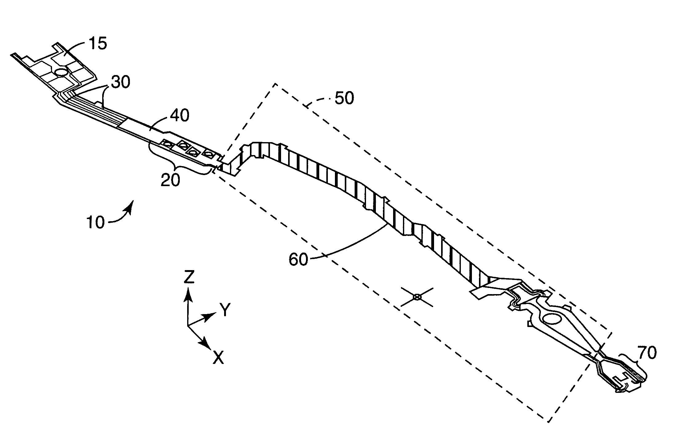
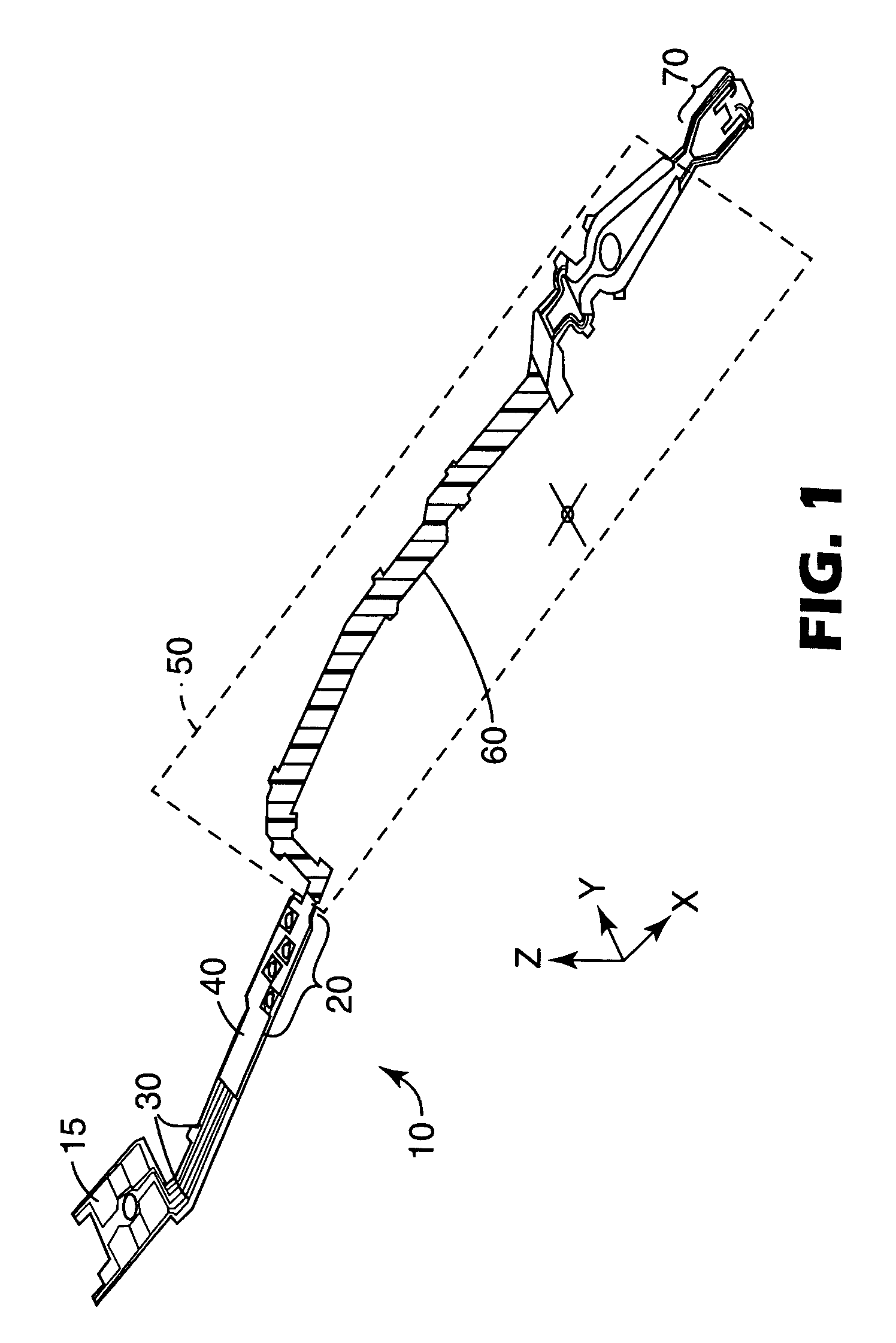
[0007]In accordance with one embodiment of the present invention, a thin conductive polymer coating is applied over a portion of a flexible circuit in the non-critical region to reduce the measured surface voltage by enabling the flow of tribocharging induced charges on the coated surface allowing faster discharge from the affected area when contacted by a conducting, grounded probe. The conductive layer limits the rate of discharge due to its inherent resistivity. If the coating is in contact with a conductive polymer stripe, the built-up charges can also be discharged through probes contacting the coated, non-critical surface. The resulting circuits have added ESD protection because the conductive surface will enable discharge of any charges developed on its surface by starting the discharge as soon as they are created, thus lowering the peak voltage on the surface by enabling and controlling voltage level decay. Since the available energy to damage the GMR head is proportional to the voltage level when the energy is coupled through the sensitive GMR sensor, the total energy is reduced.
[0008]The thin conductive film will significantly reduce surface resistivity of the insulating materials from about 1011 ohms to about 1014 ohms to a range of about 104 ohms to about 108 ohms.

Problems solved by technology

Damage caused by ESD accounts for a large portion of the HGA yield losses in the HDD industry, which has a significant impact on industry profits.
However, it has now been discovered that a flexible circuit having a thin conductive polymer coating applied over a portion of a flexible circuit in the non-critical region reduces the measured surface voltage substantially.

Method used


Image

  • Flexible circuit with electrostatic damage limiting feature
  • Flexible circuit with electrostatic damage limiting feature
  • Flexible circuit with electrostatic damage limiting feature

Examples


examples

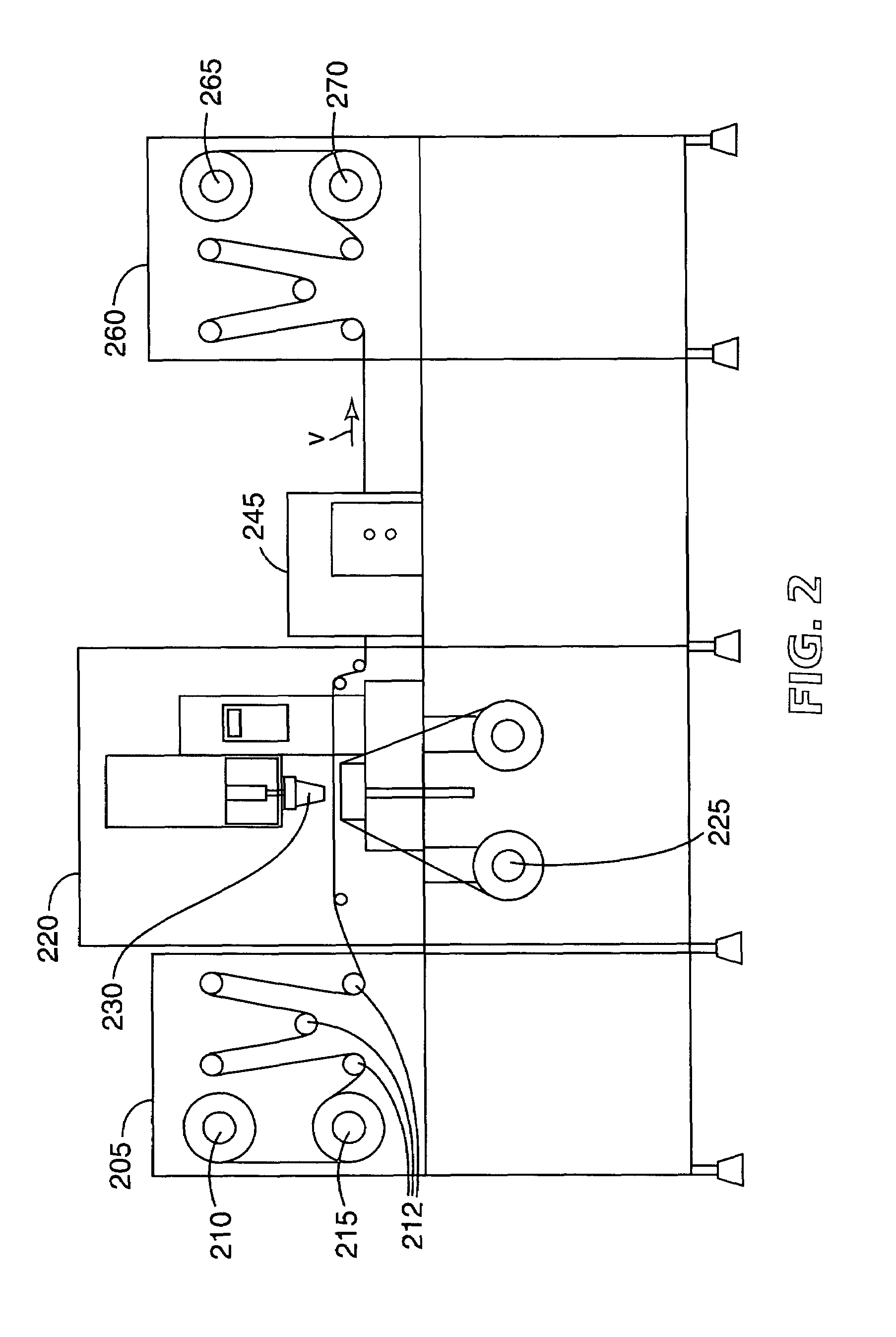
[0020]The preferred conductive polymer composition comprises a mixture of a conductive polymer, a nonionic binder material, a wetting agent, and a film former.

[0021]One preferred conductive polymer is an aqueous dispersion of poly-3-4-ethylenedioxythiophene complexed with polystyrene sulfonate available from Bayer Corporation of Pittsburgh, Pa. known as Baytron™ P-LS having low residual ionic content. The conductive polymer suspension is supplied having about 1% to about 4% solids by weight.

[0022]A preferred nonionic binder material is Rhoplex HA-16, which is a self-crosslinking acrylic binder available from Rohm and Haas Company of Philadelphia, Pa.

[0023]The preferred wetting agent is Zonyl® FSN available from Dupont Chemical Company, Wilmington, Del. The chemical structures will be “RfCH2CH2O (CH2CH2O )xH”, where Rf=F(CF2CF2)y, where X=0 to about 25, and Y=1 to about 9. The wetting agent is used to modify surface energy at very low concentrations, and is compatible with most aqueo...


PUM

PropertyMeasurementUnit
surface voltageaaaaaaaaaa
thicknessaaaaaaaaaa
thicknessaaaaaaaaaa

Abstract

A flexible circuit incorporating an electrostatic discharge limiting feature, comprising a dielectric substrate selected from polyimide or liquid crystal polymer film having at least one conductive trace coated on at least one surface of the substrate wherein the discharge limiting feature includes a thin conductive polymer coating selectively applied over a at least a portion of the non-critical region of the circuit, said feature reducing the surface resistivity of the circuit to about 104 ohms to about 108 ohms and having tribocharging of less than about 50 V.

Description

CROSS-REFERENCE TO RELATED APPLICATION[0001]This application is a divisional of U.S. Ser. No. 10 / 255,507, filed Sep. 26, 2002, now U.S. Pat. No. 6,815,620, as a continuation-in-part of U.S. Ser. No. 09 / 823,220, filed on Mar. 29, 2001, now U.S. Pat. No. 6,459,043.BACKGROUND OF THE INVENTION[0002]Microflex circuits are widely used for applications such as integrated circuit (IC) packages, inkjet cartridges, hard disk drives (HDD), medical devices and other advanced flex circuit-based electrical connections. Such connections require electrical static discharge (ESD) protection during product manufacturing and assembly comprising insulating materials (plastic, polymers) and manual operations. ESD concerns are amplified in hard disk drive manufacturing environments and applications, especially for head gimbal assemblies (HGA) using giant magnetorestrictive read (GMR) sensors in the sliders. For current commercial hard disk drive (HDD) product platforms at 40 or 60 gigabit / in2 [(GB) / in2],...

Claims


Application Information

Patent Timeline
Patent Type & Authority Patents(United States)
IPC IPC(8): B05D5/12B41M1/12G11B5/40G11B5/48H05K1/00H05K1/02H05K1/16H05K3/00H05K3/28H05K9/00
CPCG11B5/40G11B5/48G11B5/4806H05K1/0259H05K3/0091H05K9/0067H05K1/0393H05K1/167H05K3/1275H05K3/28H05K2201/0323H05K2201/0329H05K2203/0534H05K2203/095H05K2203/1545G11B5/484
Inventor SCHEIBNER, JOHN B.ZHANG, KEEE, CHEE TATMOK, JUANG MENGLEE, YONG PENG
Owner 3M INNOVATIVE PROPERTIES CO
Why Eureka
Try Eureka