EMI shield including a lossy medium

a lossy medium and emi shield technology, applied in the field of emi shield including a lossy medium, can solve the problems of reducing the efficiency of the ground conduction path through the enclosure, difficult to achieve effective shielding, and typically generating undesirable electromagnetic energy of electronic equipment, so as to enhance the performance of emi shield and reduce the effect of resonant “peaks

Inactive Publication Date: 2006-11-14
LAIRD TECH INC
View PDF21 Cites 81 Cited by
  • Summary
  • Abstract
  • Description
  • Claims
  • Application Information

AI Technical Summary

Benefits of technology

[0009]In general, the present invention relates to an EMI shield, such as a highly-conductive metal enclosure or cage, that incorporates an electrically absorbing or lossy material to absorb a portion of the EMI, thereby enhancing the performance of the EMI shield over a range of operational frequencies. The absorbing material may remove a portion of the EMI from the environment by the process of ohmic loss—dissipating a portion of the EMI in the form of thermal heating. The absorbing material, when placed within a conductive cavity may also alter the resonant characteristics of the cavity to reduce resonant “peaks” of the electromagnetic fields within the cavity, and / or to translate in frequency, a resonant peak or cutoff.

Problems solved by technology

During normal operation, electronic equipment typically generates undesirable electromagnetic energy that can interfere with the operation of proximately located electronic equipment due to EMI transmission by radiation and conduction.
Since such enclosures often include gaps or seams between adjacent access panels and around doors, effective shielding is difficult to attain, because the gaps in the enclosure permit transference of EMI therethrough.
Further, in the case of electrically conductive metal enclosures, these gaps can inhibit the beneficial Faraday Cage Effect by forming discontinuities in the conductivity of the enclosure which compromise the efficiency of the ground conduction path through the enclosure.
Moreover, by presenting an electrical conductivity level at the gaps that is significantly different from that of the enclosure generally, the gaps can act as slot antennae, resulting in the enclosure itself becoming a secondary source of EMI.
Practical applications, however, result in an enclosure constructed of a finitely-conducting material and having some apertures.
As the frequencies of operation increase, however, the associated wavelengths of induced EMI decrease, leading to a reduction in shielding effectiveness for any non-ideal EMI enclosure.
These resonance effects, by increasing the peak energy levels within the enclosure, can reduce the apparent shielding effectiveness at the resonant frequencies because the same enclosure is shielding a larger source of EMI—the resonant peak electromagnetic energy.
The MSA-recommended EMI cage 50 offers a design level of shielding effectiveness for GBIC operations at 1 Gbps; however, as operating frequencies increase, the shielding effectiveness of the recommended EMI cage, without modification, will be inadequate.

Method used


Image

  • EMI shield including a lossy medium
  • EMI shield including a lossy medium
  • EMI shield including a lossy medium

Examples


Embodiment Construction

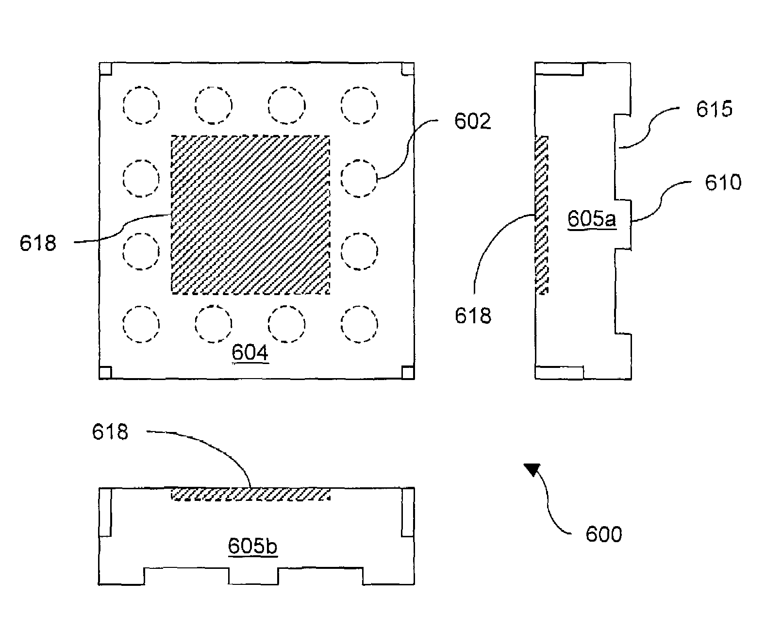
[0038]Lossy materials can be used to suppress EMI transmissions, for example, by converting the electromagnetic energy into another form of energy, such as thermal energy. The electromagnetic fields can induce electrical currents to flow within the lossy material having a finite electrical conductivity, resulting in ohmic losses. In one embodiment, the lossy material can be composed of ferrite-like material mixed in an elastomer, such as a resin binder. In other embodiments, the lossy material can be composed of a lossy filler material, such as carbon powder mixed in an open-celled reticulated foam. The lossy materials can be configured in sheet form or in a liquid form for coating a substrate. Some examples of lossy materials are electrically conductive material, carbon, iron, carbonyl iron powder, sendust, ferrites, iron silicide, magnetic alloys, magnetic flakes, steel wool, and combinations thereof. Other examples of lossy materials include carbon-impregnated rubber, ferrite in ...


PUM


Abstract

Lossy materials can be used to suppress EMI transmission. Disclosed are methods for applying lossy materials to EMI shielded enclosures to improve EMI shielding effectiveness and the EMI shielded enclosures so produced. In some embodiments, the EMI shielded enclosure includes a printed-circuit board mountable device. In one embodiment, lossy material can be applied to the interior of an EMI shielded enclosure using an adhesive. In another embodiment, lossy materials can be applied to the exterior of the EMI enclosure to suppress EMI incident upon the EMI shielded enclosure, thereby reducing the susceptibility of electronics contained within the EMI shielded enclosure. In yet another embodiment, lossy materials can be applied to both the interior and exterior of the EMI enclosure.

Description

CROSS-REFERENCE TO RELATED APPLICATION[0001]This application claims the benefit of and priority to U.S. Provisional Application Ser. No. 60 / 340,343, filed on Dec. 14, 2001, the disclosure of which is incorporated herein by reference in its entirety.FIELD OF THE INVENTION[0002]The present invention relates to generally to electronic component packaging and, more specifically, to electronic component packages that are shielded to protect against electromagnetic interference (EMI).BACKGROUND OF THE INVENTION[0003]As used herein, the term EMI should be considered to refer generally to both electromagnetic interference and radio frequency interference (RFI) emissions, and the term “electromagnetic” should be considered to refer generally to electromagnetic and radio frequency.[0004]During normal operation, electronic equipment typically generates undesirable electromagnetic energy that can interfere with the operation of proximately located electronic equipment due to EMI transmission by...

Claims


Application Information

Patent Timeline
Patent Type & Authority Patents(United States)
IPC IPC(8): H05K9/00G02B6/42H01L23/552
CPCG02B6/4277H01L23/552H05K9/0058H05K9/0088Y10T428/25H01L2924/16152H05K9/00
Inventor VAN HAASTER, PHILIPNAKAUCHI, EDWARDJOHNSON, RICHARD NORMAN
Owner LAIRD TECH INC
Why Eureka
Try Eureka