
Feeder controls for a forage harvester

a technology of feeder control and forage harvester, which is applied in the direction of threshers, using reradiation, instruments, etc., can solve the problems of serious reaction problems, and achieve the effect of improving the reaction speed of the arrest system and the volume of oil

Inactive Publication Date: 2006-11-28
BLUE LEAF I P INC +1
View PDF22 Cites 24 Cited by
  • Summary
  • Abstract
  • Description
  • Claims
  • Application Information

AI Technical Summary

Benefits of technology

[0015]This arrangement does not require any mechanical clutches or pawls to arrest the feeder means. The particular location of the arrest means precludes the escape of blocked oil via the flushing circuit, such that the motor can be stopped more abruptly and the passage of foreign objects into the crop processing means is prevented.
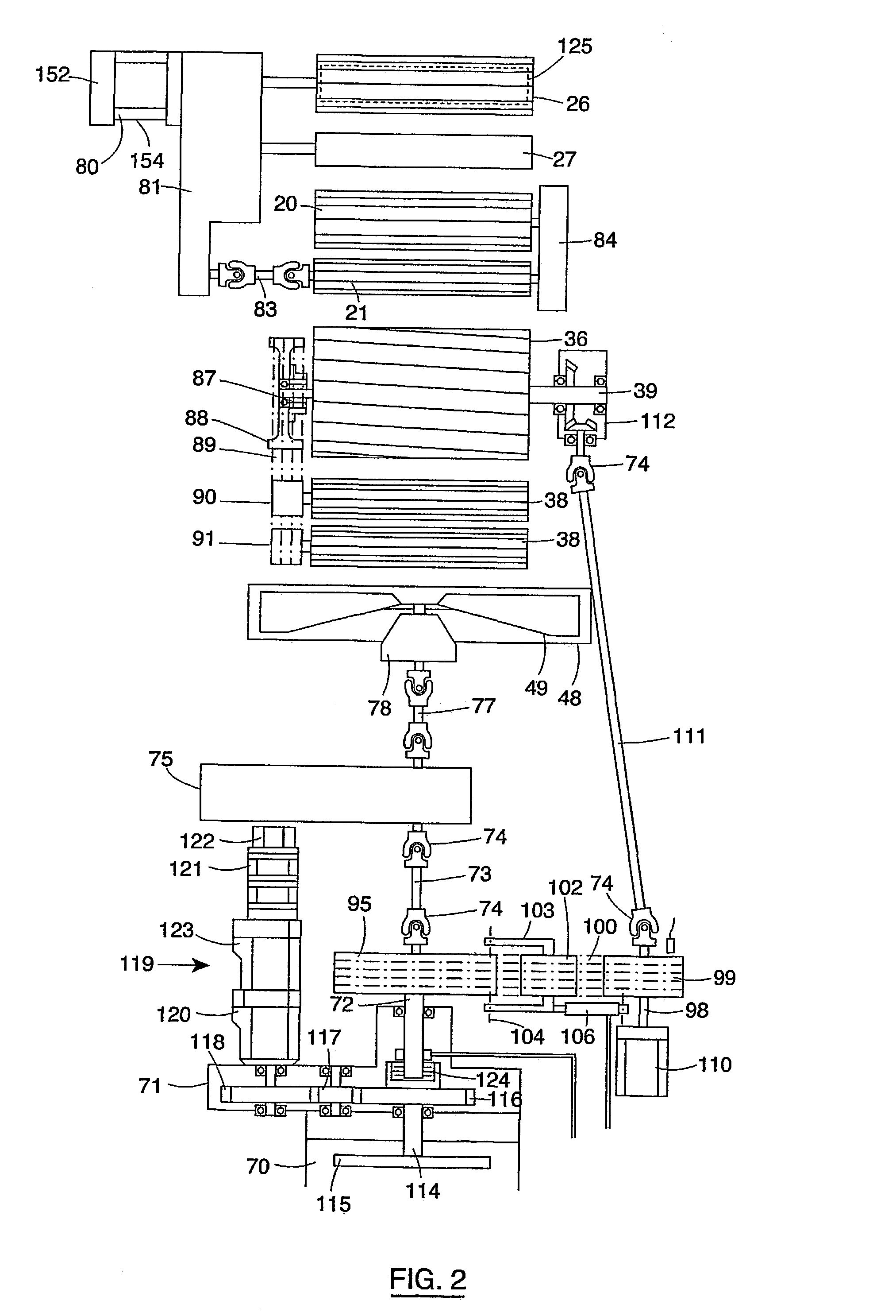
[0016]The flushing means may comprise a flushing valve arranged between the high pressure and the low pressure lines of the motor and the arrest means an arrest valve operable to block the high or low pressure line of the motor. Advantageously these valves are incorporated into a single valve assembly which is mounted to the motor housing. In this manner the volume of oil between the motor and the arrest valve can be limited, thus improving the reaction speed of the arrest system.
[0018]Where the arrest system has to assume a high energy load, it may be advantageous to use an arrest valve which is pilot controlled by a solenoid actuated control valve. To improve the reaction time of such pilot controlled valve it may be useful to provide the circuitry adjacent the motor with a hydraulic accumulator which is connected via the solenoid actuated valve to the pilot controlled valve.

Problems solved by technology

However, it has been experienced that serious problems as to reaction. speed and life time emerged when such systems are applied to the present-day high capacity harvesters in which the rotating feedrolls have a greater kinetic energy.

Method used


Image

  • Feeder controls for a forage harvester
  • Feeder controls for a forage harvester
  • Feeder controls for a forage harvester

Examples


Embodiment Construction

[0025]The terms “front”, “rear”, “forward”, “rearward”, “right” and “left” used throughout this specification are determined with respect to the normal direction of movement of the machine in operation and are not to be construed as limiting terms.

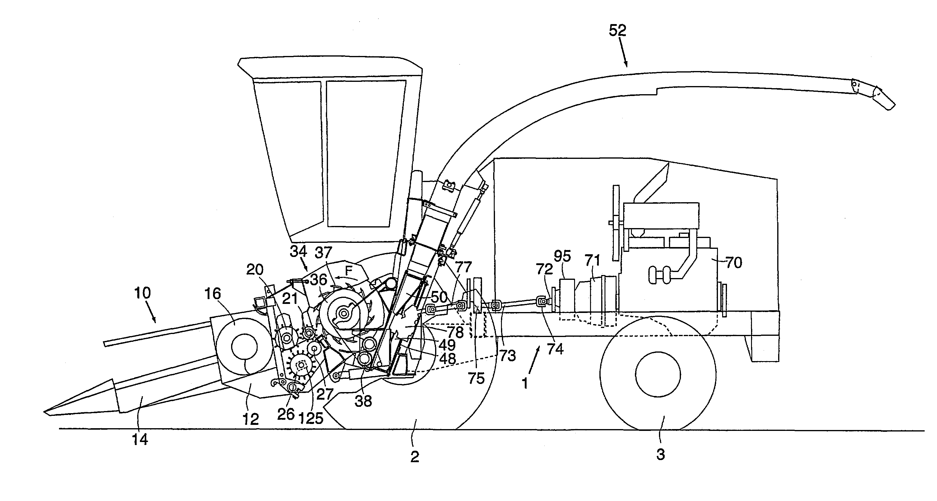
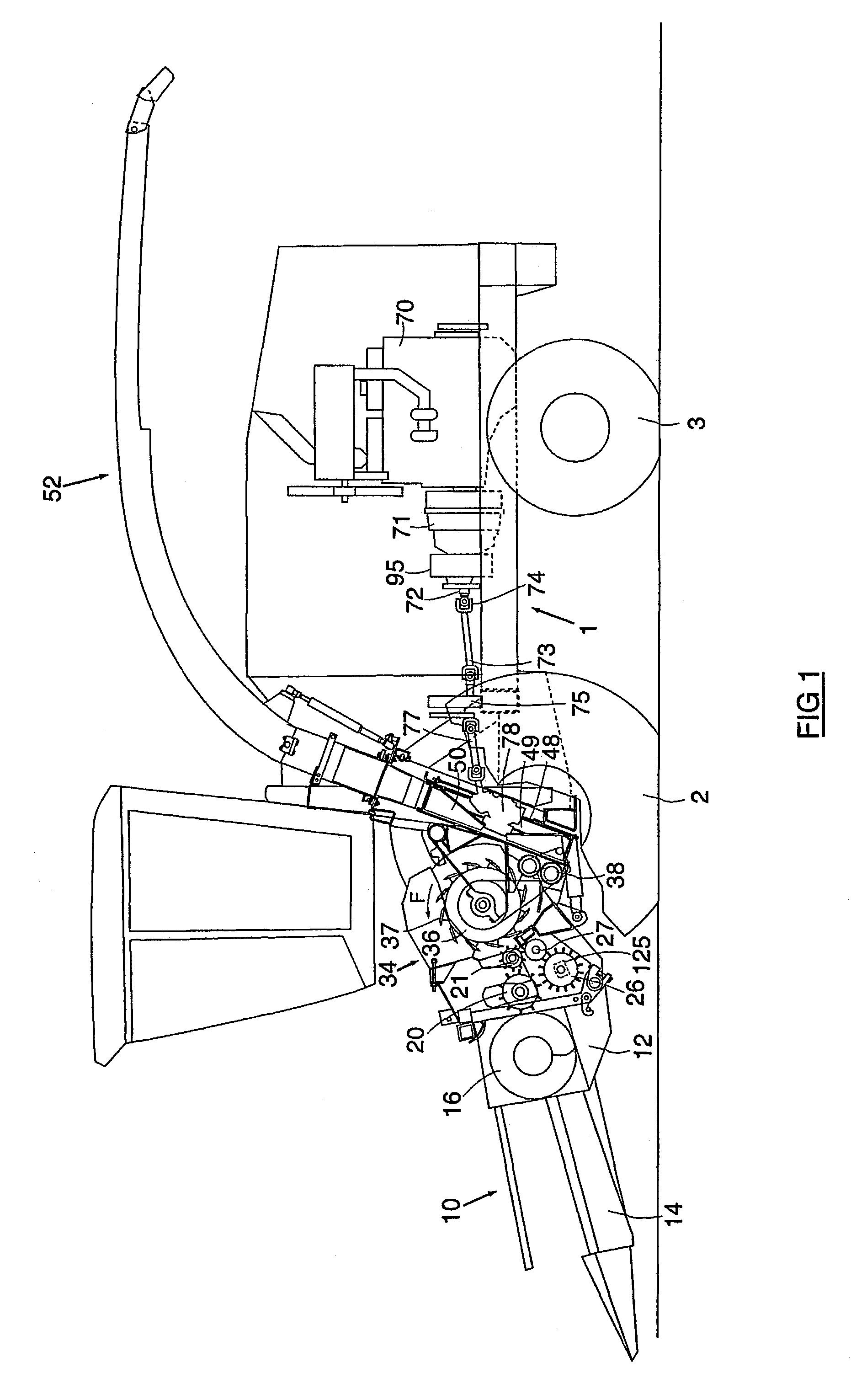
[0026]In FIG. 1, there is shown a forage harvester having a main frame 1 on which there are mounted ground engaging traction wheels 2 and steering wheels 3. The forage harvester is shown equipped with a crop collecting apparatus, in the form of a row crop attachment 10, suitable for the harvesting of maize, but which can be replaced with a conventional windrow pick-up device or a conventional cutter bar attachment, depending on the type of crop to be harvested. Customarily, the row crop attachment 10 comprises an attachment frame 12, which supports a plurality of row crop units 14, operable to harvest maize stalks from the field and to convey the same rearwards to an auger 16, which in turn delivers the crop material to the bite of feeder ...


PUM


Abstract

An agricultural harvesting machine, such as a forage harvester comprises a set of feedrolls (20, 21, 26, 27) for feeding harvested crop material to a rotating cutterhead (36). The feedrolls are driven by a hydraulic drive means comprising a hydrostatic pump (123) coupled to the engine (70) of the harvesting machine, a hydrostatic motor (80) coupled to said feeder means (20, 21, 26, 27) and hydraulic circuitry (142, 143, 152) interconnecting the pump and the motor. The circuitry comprises a feeder arrest valve (165) which is operable to interrupt the oil flow from said hydrostatic motor (80), thereby arresting said feedrolls (20, 21, 26, 27). The hydrostatic motor (80) is provided with a flushing valve (156) for diverting part of the oil flow in said circuitry through said motor for lubricating and cooling the latter. The arrest valve (165) is provided in said circuitry (142, 143, 152) between the hydrostatic motor (80) and the flushing valve (156). This arrangement allows for an immediate and efficacious arresting of the feedrolls upon detection of a foreign object in the harvested crop.

Description

TECHNICAL FIELD OF THE INVENTION[0001]The present invention relates to agricultural harvesting machines provided with feeder means for feeding harvested crop material to crop processing means. More particularly, it relates to feeder means which are driven by a hydraulic motor and which are provided with means for immediately arresting said feeder means upon detection of a foreign object in the crop material.BACKGROUND ART[0002]It is well known in the art to provide agricultural harvesting machines, such as forage harvesters, with an apparatus for detecting foreign material in the stream of crop material which is being fed to a crop processing unit, such as a rotating cutterhead co-operating with a stationary shear bar. Such detector apparatus may be a metal detector of the type described in EP-B-0,102,665. The signal generated by this detector is fed to feeder arrest means, which provoke an immediate stop of the means feeding the crop material to the cutterhead. Thus is prevented th...

Claims


Application Information

Patent Timeline
IPC IPC(8): A01D69/00A01D75/18A01F29/14A01F29/16
CPCA01F29/14A01F29/16F16H61/4104
Inventor AMEYE, DANNY R.DENEIR, STEPHAN P.
Owner BLUE LEAF I P INC
Learn More