Driving method of piezoelectric actuator, piezoelectric actuator, and disk recording and reproducing apparatus using the same

a piezoelectric actuator and driving method technology, applied in the direction of piezoelectric/electrostrictive device details, instruments, device details, etc., can solve the problems of insufficient positioning precision that cannot be assured by the conventional vcm alone, teaches nothing about the driving method as piezoelectric actuators, and can no longer guarantee the insulation resistance. deterioration, etc., to achieve the effect of large displacemen

Inactive Publication Date: 2006-11-28
PANASONIC CORP
View PDF16 Cites 7 Cited by
  • Summary
  • Abstract
  • Description
  • Claims
  • Application Information

AI Technical Summary

Benefits of technology

[0010]It is hence a primary object of the invention to present a driving method of piezoelectric actuator stable for a long period of time and capable of obtaining a large displacement continuously by recovering from deterioration of polarization characteristic in a state of mounting a piezoelectric actuator using a piezoelectric element fabricated by thin-film technology, a piezoelectric actuator, and a disk apparatus using the piezoelectric actuator.
[0014]By this driving method, since the piezoelectric element is polarized in a direction of smaller absolute value of the coercive field, the polarization is not disturbed if a position control voltage is applied in a direction of smaller value of the coercive field, and hence displacement is not changed. On the other hand, in a direction of larger absolute value of the coercive field, the position control voltage is smaller than the voltage inducing inversion of polarization, and the polarization is hardly disturbed. As a result, the piezoelectric element of stable displacement can be driven.
[0019]By this driving method, by applying the polarization recovery voltage for recovery from deterioration of polarization to the piezoelectric element by superposing on the position control voltage, by applying by changing over with the position control voltage, or by applying when the position control voltage is not applied, if the displacement deteriorates when the piezoelectric element is driven, the piezoelectric element can be recovered from deterioration of polarization while the piezoelectric actuator is being assembled in the disk apparatus. Thus, the piezoelectric actuator of high precision can be realized at high reliability.

Problems solved by technology

As the recording density is enhanced, however, sufficient positioning precision can be no longer assured by the conventional VCM alone.
In this method, prior to use of the piezoelectric element, it is stabilized by applying sinusoidal waves ranging from, for example, 0 V to 150 V. However, when such high voltage is applied for 1 hour, or preferably as long as 10 hours, the insulation resistance may deteriorate in the case of the piezoelectric element fabricated by the thin film technology.
This publication, however, teaches nothing about driving method as piezoelectric actuator for stabilizing polarization of piezoelectric element or preventing deterioration of insulation resistance.

Method used


Image

  • Driving method of piezoelectric actuator, piezoelectric actuator, and disk recording and reproducing apparatus using the same
  • Driving method of piezoelectric actuator, piezoelectric actuator, and disk recording and reproducing apparatus using the same
  • Driving method of piezoelectric actuator, piezoelectric actuator, and disk recording and reproducing apparatus using the same

Examples


first exemplary embodiment

[0053

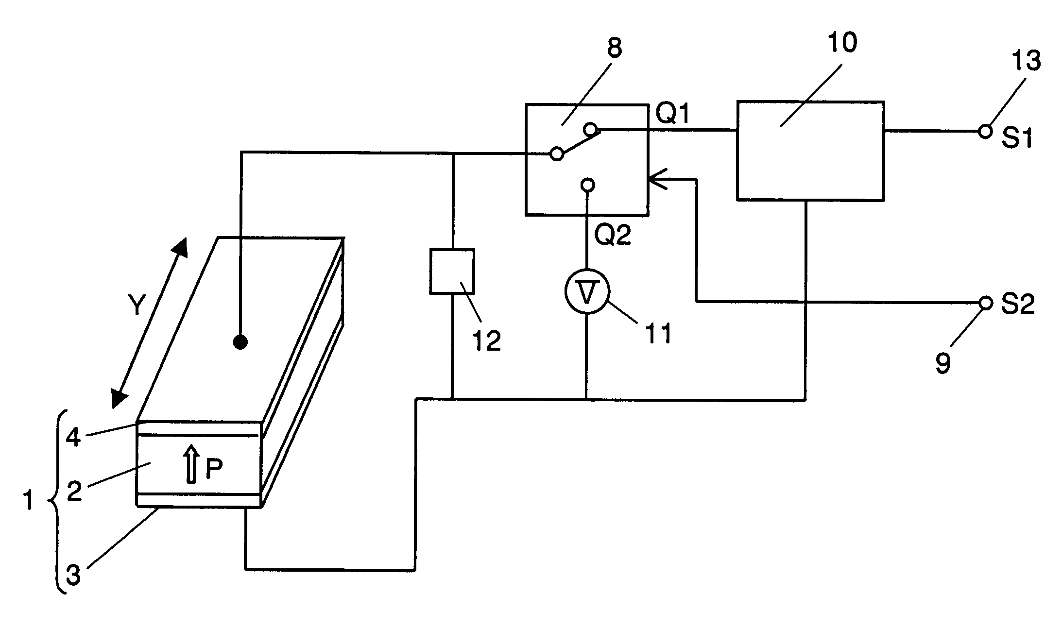
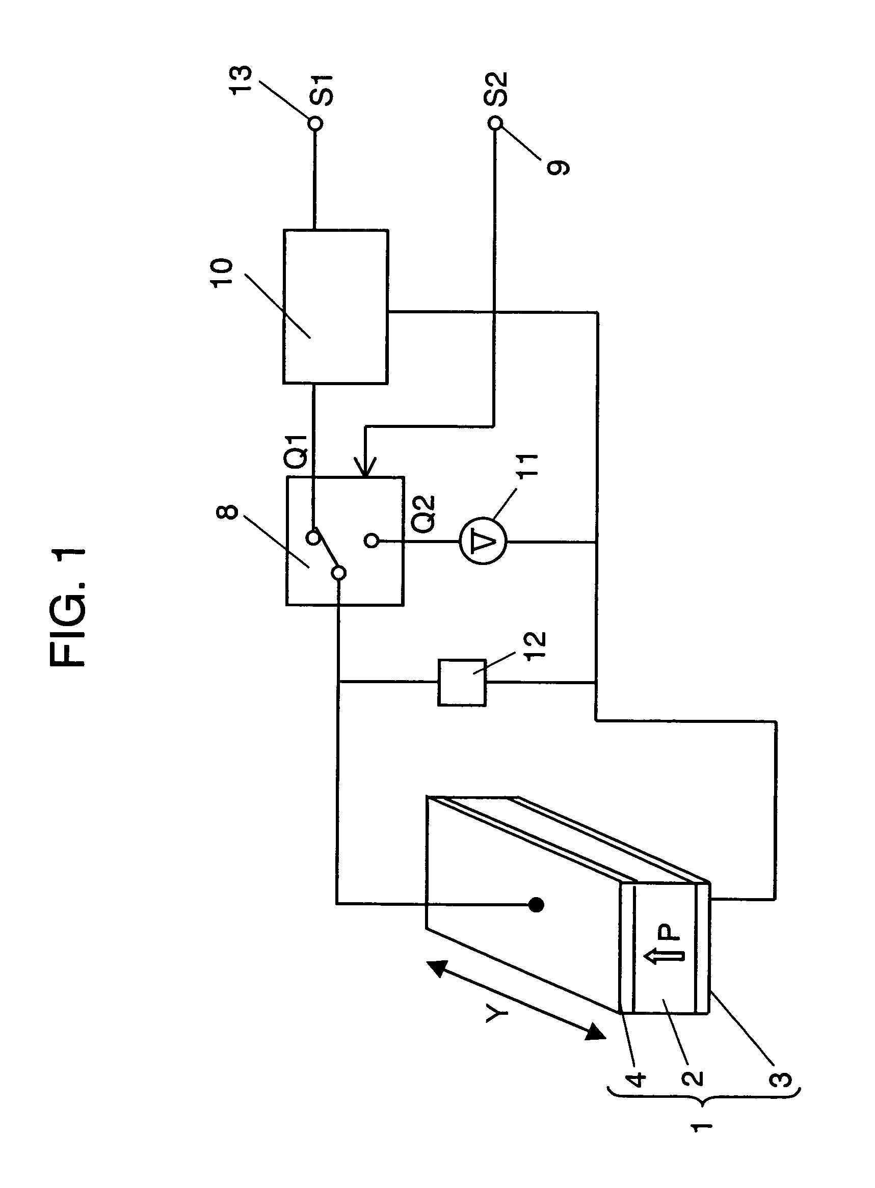
[0054]FIG. 1 is a control circuit block diagram of a piezoelectric actuator in a first exemplary embodiment of the invention. A piezoelectric element 1 is composed of a first conductor 3, a second conductor 4, and a piezoelectric thin film 2 enclosed between them. The first conductor 3, second conductor 4, and piezoelectric thin film 2 are formed by sputtering or other thin-film technology, and processed in a box shape as shown by photolithography and etching. Dimensions of the piezoelectric element 1 are 2 mm in the length direction of the direction causing displacement, for example, (direction indicated by Y in FIG. 1), and about 3 μm in thickness. Usually, to make use of the piezoelectric action, it is necessary to induce initial polarization in the piezoelectric element 1. In FIG. 1, the polarization direction is the thickness direction as indicated by arrow P in the diagram. As the hysteresis characteristic, the absolute value of the positive coercive field EC2 has a small...

second exemplary embodiment

[0066

[0067]FIG. 5 is a perspective view of principal parts showing an example of impression of piezoelectric actuator in a second exemplary embodiment of the invention, and a head support mechanism mounting this piezoelectric actuator, in a disk apparatus. This disk apparatus is characterized as being composed of two actuators, that is, the actuator of the conventional VCM and the piezoelectric actuator of the invention.

[0068]A head support mechanism 100 is composed of a suspension 104 of relatively low rigidity, a plate spring 105, an arm 106 of relatively high rigidity, a flexure 103, a head slider 102 disposed on the flexure 103 on a side facing a disk 200, a head (not shown) mounted on the head slider 102, and a piezoelectric element 108 adhered and fixed on the flexure 103. One end of the flexure 103 is fixed to the suspension 104. The suspension 104 is designed at a relatively low rigidity, and other end composes the plate spring 105, and this plate spring 105 is fixed to the ...

third exemplary embodiment

[0083

[0084]A third exemplary embodiment explains a structure of piezoelectric element used in the piezoelectric actuator, and results of driving method not applying polarization recovery voltage by using this structure, by referring to an example of piezoelectric element of a single-layer structure.

[0085]The piezoelectric element of this exemplary embodiment was fabricated as follows. A first conductor 3 is a platinum (Pt) film of 100 nm in film thickness, and a piezoelectric thin film 2 is a lead zirconic titanate (PZT) thin film of 3 μm in film thickness fabricated by sputtering method. First, on a magnesium oxide (MgO) single crystal substrate having (100) azimuth, a 100 nm thick Pt film is formed in (100) orientation at 600° C. In succession, a 3 μm thick PZT film is formed in (001) orientation at 600° C. As a second conductor 4, a Pt film is formed in a film thickness of 100 nm at room temperature. Then, by processing into a specified piezoelectric shape by etching, the MgO sub...


PUM

PropertyMeasurementUnit
thicknessaaaaaaaaaa
thicknessaaaaaaaaaa
thicknessaaaaaaaaaa

Abstract

In a disclosed method, a piezoelectric element 1 has an asymmetrical hysteresis characteristic of polarization-electric field different in absolute values between a coercive field of positive electric side and a coercive field of negative electric field side, and is polarized in the film thickness direction of the piezoelectric element 1 and in a direction of smaller absolute value of the coercive field, and as a position control voltage Q1 for position control by ditorting the piezoelectric element 1 in a direction orthogonal to the film thickness direction of the piezoelectric element 1, a voltage equivalent to an electric field of 0.4 or less of the coercive field value is applied in the film thickness direction of the piezoelectric element 1 in a direction of larger absolute value of the coercive field. Further, a position control voltage Q2 for recovering from deterioration of polarization of the piezoelectric element 1 is applied by superposing on the position control voltage Q1, or changing over with the position control voltage Q1, or while the position control voltage Q1 is not applied, and therefore recovering from deterioration of polarization characteristic, the displacement characteristic is stabilized for a long period of time.

Description

FIELD OF THE INVENTION[0001]The present invention relates to a piezoelectric actuator using a thin film piezoelectric element and its driving method, and a disk recording and reproducing apparatus mounting the piezoelectric actuator.BACKGROUND OF THE INVENTION[0002]Micro machines are intensively developed recently, such as ultrasmall piezoelectric actuators, motors and pumps, by utilizing the micro machine technology. Among them, the piezoelectric actuator is developed for ink jet printer or use in head positioning in a disk recording and reproducing apparatus (hereinafter called disk apparatus) in which positioning of high precision is demanded in a miniature region.[0003]For use in a disk apparatus, for example, it is developed as follows. Usually, a head for recording and reproducing information in a disk-shape recording medium (hereinafter called disk) is mounted on a head slider, and is attached to an actuator arm. By oscillating this actuator arm by a voice coil motor (hereina...

Claims


Application Information

Patent Timeline
Patent Type & Authority Patents(United States)
IPC IPC(8): H01L41/08G11B5/55H01L41/04H01L41/09
CPCG11B5/5552G11B5/4873H10N30/802H10N30/206
Inventor KITA, HIROYUKIKUWAJIMA, HIDEKI
Owner PANASONIC CORP
Why Eureka
Try Eureka