Inverter circuit for surface light source system

a technology of inverter circuit and surface light source, which is applied in the direction of electric ignition installation, mechanical equipment, machines/engines, etc., can solve the problems of increasing the overall cost of the inverter circuit, difficult to drive cold-cathode fluorescent lamps in parallel, and difficulty in constant adjustment of circuit, so as to improve the degree of freedom in selecting transformers, improve the effect of winding multiple wires and improving the degree of freedom of transformer selection

Inactive Publication Date: 2006-11-28
MASAKAZU USHIJIMA +1
View PDF20 Cites 9 Cited by
  • Summary
  • Abstract
  • Description
  • Claims
  • Application Information

AI Technical Summary

Benefits of technology

[0056]It is another object of the present invention to achieve a scheme of acquiring a high efficiency by using the secondary side circuit of a leakage flux transformer as a distributed constant power supply circuit and forming a resonance circuit between the capacitive component of the secondary side circuit and the leakage inductance, as achieved in a small inverter circuit, in an inverter circuit for high-power discharge lamps while maintaining the advantage of the transformer of lesser heat generation.
[0091]In addition, the wiring from the inverter circuit to the discharge lamp is not restricted, eliminating the layout restriction on the inverter circuit, so that the inverter circuit can be laid out at any desired position, such as at the back or at the edge of the surface light source.

Problems solved by technology

In this case, the collector resonating circuit and the resonance circuit present in the primary circuit interfere with each other, making it very difficult to adjust the circuit constant.
In either case, those inverter circuits are each designed merely in such a way that multiple small high efficiency inverter circuits are laid out in proportion to the number of cold-cathode fluorescent lamps, and are thus complicated.
It is the step-up transformer and the drive circuit in the inverter circuit for a high-power surface light source that require the cost most, so that the required use of the step-up transformer and the drive circuit causes the overall cost for the inverter circuit to increase.
While it is necessary to achieve cost reduction for an inverter circuit for discharge lamps by reducing the number of step-up transformers and drive circuits by making the power of the step-up transformers greater, it is difficult to drive cold-cathode fluorescent lamps in parallel.
In an inverter circuit for discharge lamps, like cold-cathode fluorescent lamps, which require a high voltage, it is very difficult to make the power of the step-up transformer higher for the following reason.
This naturally increases the thickness of the transformer, which is not allowed to become too thick due to the particular demand of designing liquid crystal display backlights thinner besides compactness.
Because the shape of the transformer greatly influences the parameters thereof and the relationship between the cross-sectional area of the magnetic path and the length of the magnetic path should be kept at a constant ratio, however, the shape of the transformer does not have a high degree of freedom.
It is very difficult to design a flat and high-power transformer.
The current phase of the portion of the secondary winding which is far from the primary winding is delayed from the current phase of the primary winding, so that a large portion of flux leaks from the secondary winding, thus forming a loose coupling portion.
When the self-resonance frequency becomes lower than the operational frequency of the inverter, the transformer gradually loses the step-up operation.
That is, it is the conventional knowledge that the transformation ratio should simply be increased to gain the step-up ratio, so that an insufficient step-up ratio when pointed out is coped with winding the secondary winding more.
This measure however leads to excessive winding of the secondary winding, which often results in a lower self-resonance frequency of the secondary winding.
This results in a vicious circle of suppressing the step-up ratio more.
Therefore, there is a limit to increasing the number of sections.
Needless to say, designing the transformer is difficult.
As a result, the leakage flux on the secondary winding does not become uniform, disabling the achievement of the ideal conditions to ultimately minimize the core loss.
However, with a requirement of a flat shape added to the difficult requirement that three conditions of the leakage inductance, the speed of the progressive wave (i.e., the self-resonance frequency) and the characteristic impedance should be met, it becomes harder to design a transformer which satisfies all the conditions at a time.
Generally speaking, however, when transformers with very small flux leakage are connected in parallel, the current may flow between the secondary windings of the transformers and reduce the efficiency or heat may be generated due to variations in the characteristics of the individual transformers.
With insufficient reactance, the load to be dispersed over the transformers does not become uniform, so that when multiple transformers are connected, the load is concentrated on some transformers.
The transformers to be used in this case have a small leakage inductance and are of course unsuitable for parallel connection.
To acquire parallel connection of transformers having small leakage inductance, therefore, a practical inverter circuit is difficult to design unless the parallel connection is made via ballast capacitors as shown in FIG. 20.

Method used


Image

  • Inverter circuit for surface light source system
  • Inverter circuit for surface light source system
  • Inverter circuit for surface light source system

Examples


Embodiment Construction

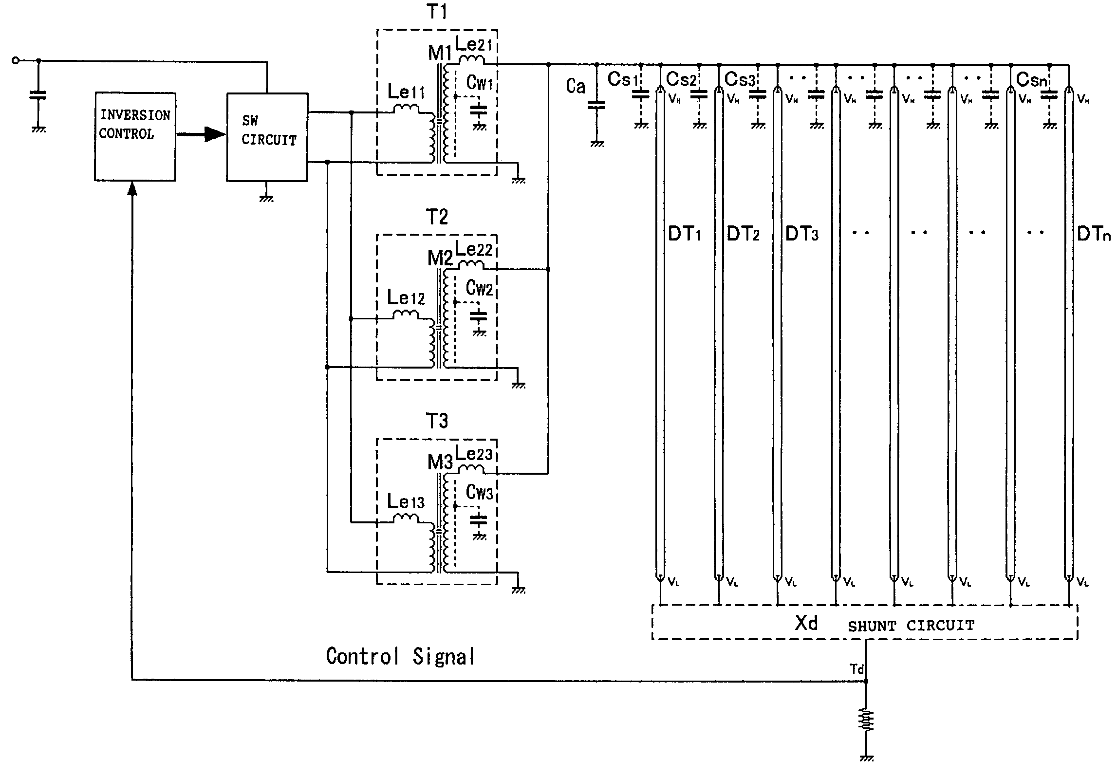
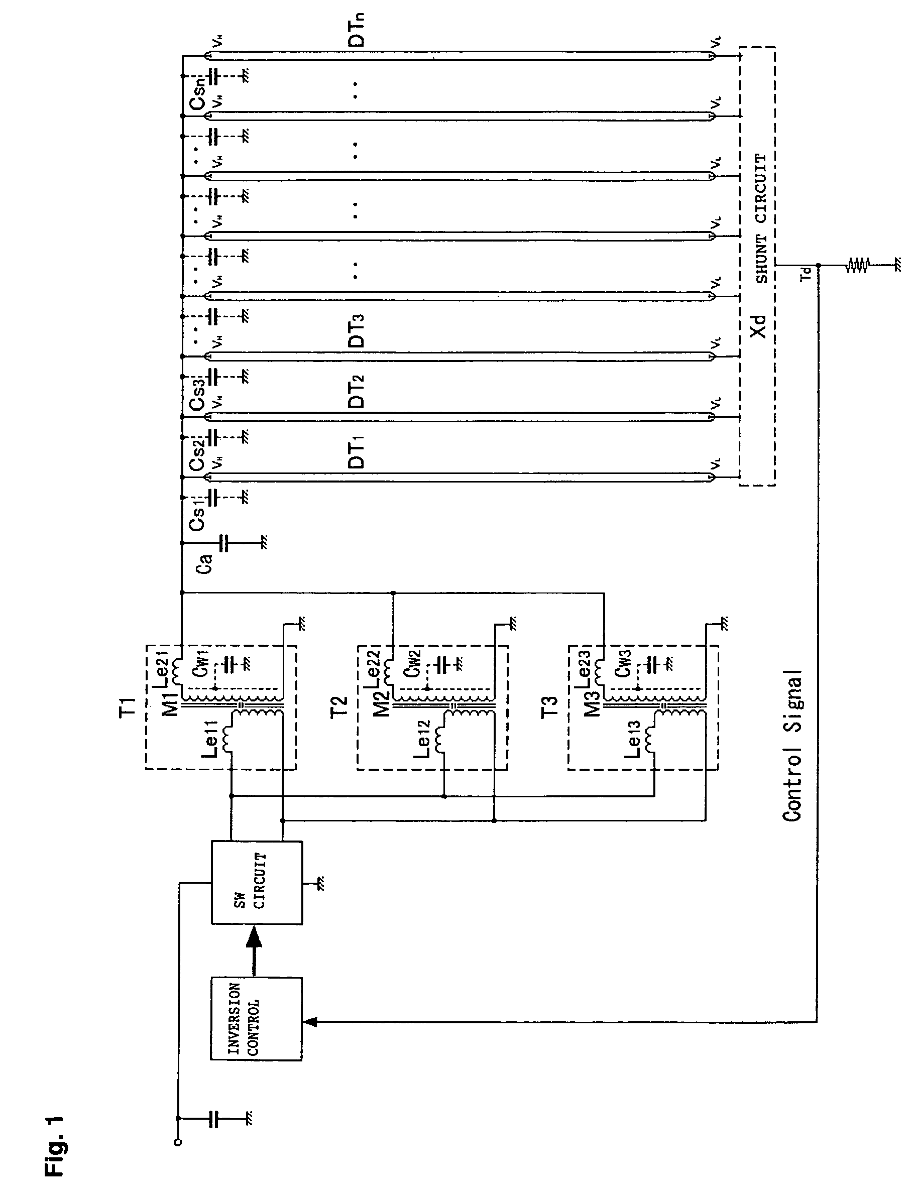
[0112]A preferred embodiment of the present invention will be described below with reference to the accompanying drawings. FIG. 1 illustrates one embodiment of the present invention with a transformer shown in an equivalent circuit. As the transformer is not an ideal one, it has a leakage flux which forms an inductance or leakage inductance.

[0113]The leakage inductance is equivalent to choke coils inserted at the output of the transformer which are indicated by Le11 to Le13 and Le21 to Le23. The self-inductances L01 to L03 of the secondary windings are the series-combined values of mutual inductances M1 to M3 and the leakage inductances Le21 to Le23, though not described.

[0114]Cw1 to Cw3 are the distributed capacitances of the secondary windings, which, together with the self-inductances of the secondary windings, form the self-resonance frequency fp. Xd is a shunt circuit which lights cold-cathode fluorescent lamps in parallel and is adequately inserted according to the characteris...


PUM

PropertyMeasurementUnit
poweraaaaaaaaaa
thicknessaaaaaaaaaa
leakage inductanceaaaaaaaaaa

Abstract

An inverter circuit for discharge lamps, in which transformers are separated into multiple small or middle-sized transformers connected to one another to provide a high-power transformer equivalent to a large transformer. The inverter circuit includes a plurality of leakage flux step-up transformers each having a magnetically continuous central core, a primary winding, and a distributed-constant secondary winding, wherein a part of a resonance circuit is formed among a leakage inductance produced on the secondary winding side, a distributed capacitance of the secondary winding and a parasitic capacitance produced around a discharge lamp close to a proximity conductor, and as the resonance circuit resonates, the secondary winding has a close coupling portion in a vicinity of the primary winding which has a magnetic phase close to that of the primary winding and magnetically close couples with the primary winding.

Description

[0001]This application claims priority to Japanese Patent application No 2003-365326 filed on Oct. 24, 2003.TECHNICAL FIELD[0002]The present invention relates to an application of the invention described in Japanese Patent Application No. 2004-003740 (corresponding to U.S. Ser. No. 10 / 773,230) and pertains to an inverter circuit for discharge lamps, such as a cold-cathode fluorescent lamp, an external electrode cold-cathode fluorescent lamp, and a neon lamp, and an inverter circuit for a high-power surface light source system which emits light using multiple discharge lamps.BACKGROUND OF THE INVENTION[0003]Recently, the use of multiple cold-cathode fluorescent lamps in a surface light source such as a liquid crystal display backlight becomes popular, which demands a high-power inverter circuit.[0004]A high-power inverter circuit is generally realized by enlarging a step-up transformer and its drive circuit. Because even a slight power loss in a high-power inverter circuit leads to g...

Claims


Application Information

Patent Timeline
Patent Type & Authority Patents(United States)
IPC IPC(8): F02P15/00H05B37/02H05B39/04H05B41/00H05B41/36H05B41/24H01F38/08H02M7/493H05B41/26H05B41/282
CPCH05B41/2822H05B41/26
Inventor USHIJIMA, MASAKAZUKIJIMA, MINORU
Owner MASAKAZU USHIJIMA
Why Eureka
Try Eureka