Insulation and integrated heat sink for high frequency, low output voltage toroidal inductors and transformers

a toroidal inductors and transformer technology, applied in transformers, transformer/inductance details, electrical equipment, etc., can solve the problems of reducing convective heat transfer, difficulty in removing heat from transformers, and several limitations of bobbin-wound transformers, so as to improve power density, improve thermal performance, and reduce copper consumption

Inactive Publication Date: 2006-11-28
ASTEC INT LTD
View PDF15 Cites 15 Cited by
  • Summary
  • Abstract
  • Description
  • Claims
  • Application Information

AI Technical Summary

Benefits of technology

[0010]It is one advantage of the present invention to provide a transformer with improved thermal performance.
[0011]It is another advantage of the present invention to provide a transformer having improved power densities.
[0012]It is yet another advantage of the present invention to provide a transformer that can be adapted to have a variety of foot prints.
[0013]It is an advantage of the present invention to provide a transformer that uses less copper than conventional bobbin-wound transformers while providing sufficient cooling to the windings and core of the transformer.
[0014]It is yet another advantage of the present invention to provide a transformer that can be constructed for lower cost than bobbin-wound transformers.
[0015]It is another advantage of the present invention to provide a transformer having high conversion efficiencies.

Problems solved by technology

However, bobbin-wound transformers have several limitations.
Several of these limitations result from the difficulty in removing heat from the transformers.
Insulating layers that cover the winding wires hinder conduction of heat from the wires, while the windings interfere with air flow to inner layers of the windings and thus decrease convective heat transfer.
As a result of problems with cooling bobbin-wound transformers, there are electrical conversion and material use inefficiencies that either limit the use or operation of these transformers, limit the power density, or require more space or additional resources to provide adequate cooling.
Toroidal transformers have been developed to address the problems with bobbin-wound transformers, but these too have problems.
However, the resulting transformers have serious problems in modern high density switching power supply applications.
Such transformers are bulky and are difficult to cool.
Usually the innermost winding is buried under several layers of insulation and thus suffers the most from the latter disadvantage, i.e., the heat transfer mechanism of such a construction is through all of the other upper windings and insulation layers.
However, the biggest problem in prior art toroidal transformers is the high potential safety insulation between the primary and the secondary low voltage windings.
These prior art methods still seriously affect the manufacturing yield in high volume applications.
Applying insulation layers over the primary winding using an insulation tape or film is too cumbersome while using a sleeve on one of the windings is still time consuming.
A toroidal transformer constructed using techniques suggested in above-mentioned prior art still also has thermal limitations.
Using triple insulated wires is not a viable option due to the difficulty faced in winding the wires on toroids because of the spring-back effect that occurs during winding.

Method used


Image

  • Insulation and integrated heat sink for high frequency, low output voltage toroidal inductors and transformers
  • Insulation and integrated heat sink for high frequency, low output voltage toroidal inductors and transformers
  • Insulation and integrated heat sink for high frequency, low output voltage toroidal inductors and transformers

Examples


first embodiment

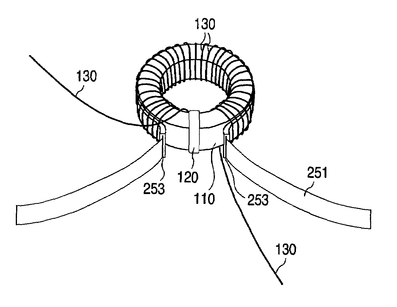
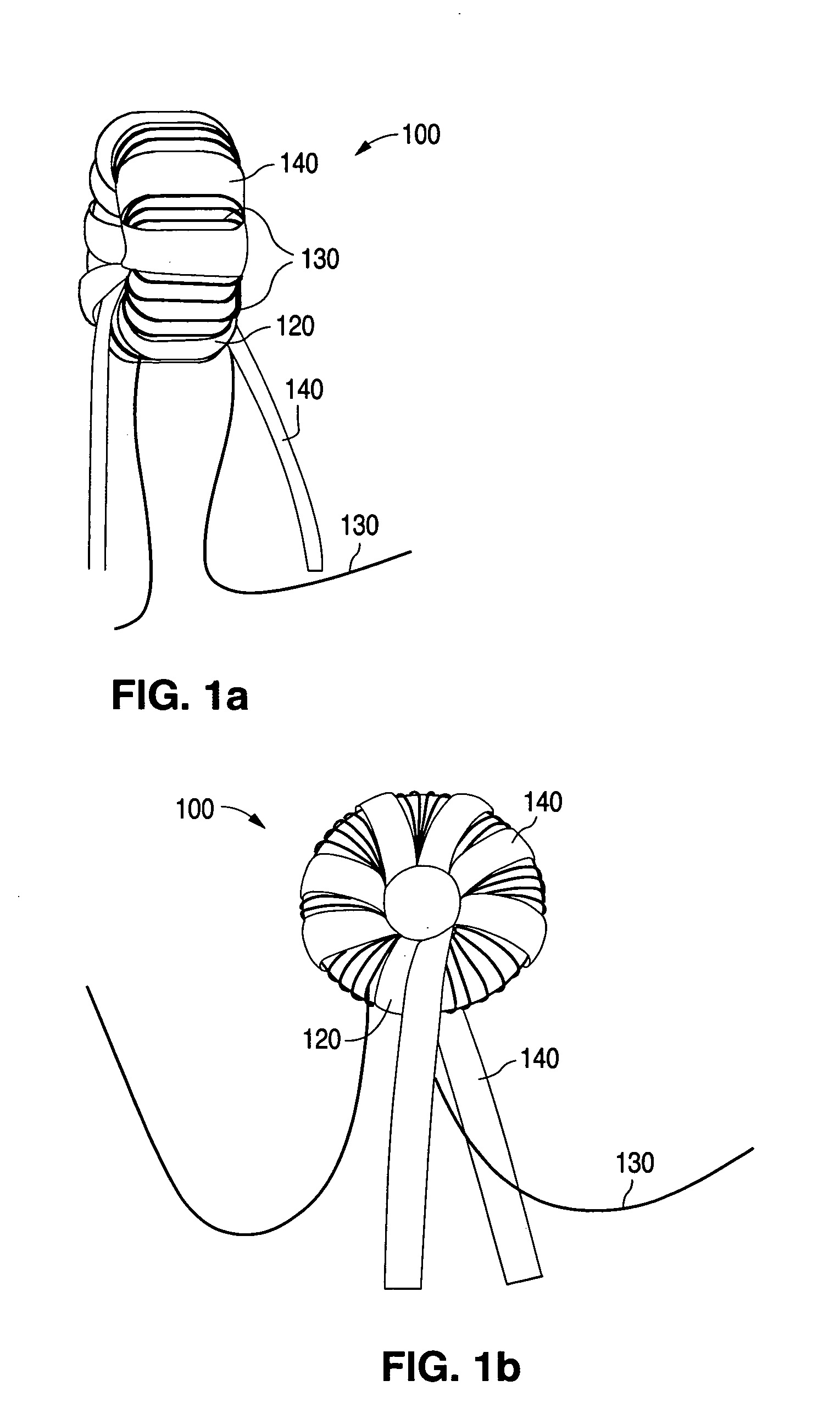
[0032]a toroidal transformer according to the present invention is now described with reference to FIGS. 1–5. FIGS. 1a and 1b are edge and left side perspective views, respectively, of a toroidal transformer 100. FIGS. 1a and 1b show primary winding 130 and a secondary winding 140 wrapped around the primary wiring to form a spiral or helix. Transformer 100 is particularly well suited for applications where sufficient air flow is available, as both the primary and secondary windings 130 and 140 are located about the outer surface of transformer 100. In addition, transformer 100 offers extremely low leakage inductance and inter-winding capacitance, and has a very small footprint.

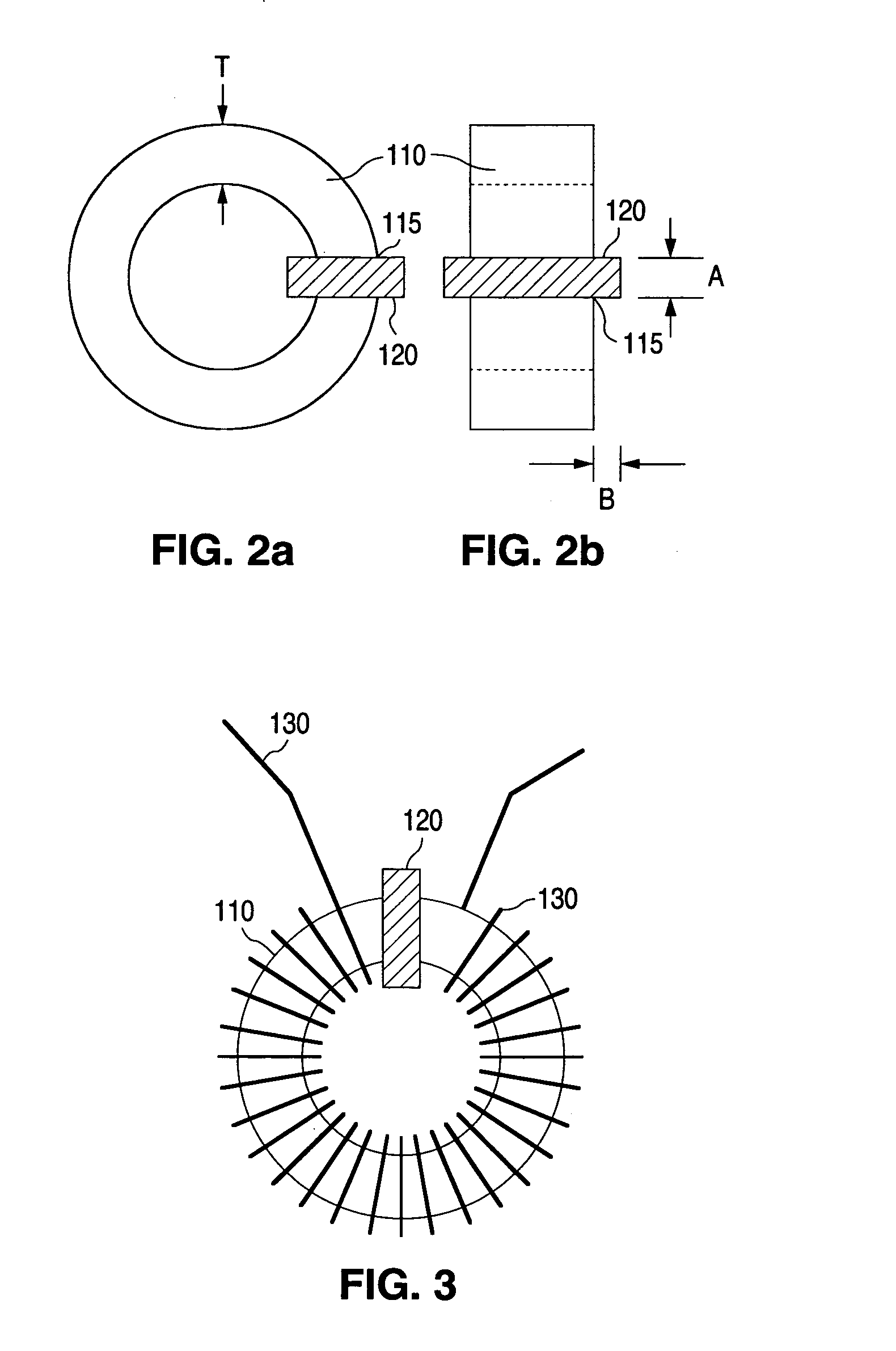
[0033]FIGS. 2a and 2b show a left side view and a top edge view, respectively, of the innermost portions of toroidal transformer 100 of the present invention. A suitable sized coated toroidal core 110 is selected to accommodate the required electrical ratings, frequency range and power handling capacity of tra...

second embodiment

[0048]To summarize, the preferred steps of the method of constructing the present invention include: (1) wrapping margin tape 120 around section 115 of coated core 110; (2) applying a thermally conductive, electrically insulating, compressible silicon sleeve 253 onto copper strap 251 to form heat sink 250; (3) wrapping the sleeve 253 portion of heat sink 251 around the outer circumference of core 110 so the exposed ends 255 of strap 251 extend from the outer circumference adjacent margin tape 120 on the top edge of core 110; (5) tightly winding primary winding 130 on core 110 with sleeved portion of heat sink 250 sandwiched between core 110 and primary winding 130; (6) applying a plurality of layers of reinforced insulating sleeve 143 onto a copper strip 141 to form secondary winding 140; and (6) wrapping the sleeved portion of secondary winding 140 over primary winding 130 to form a helix or spiral with the exposed ends of strip 141 extending from the outer circumference of core 11...


PUM

PropertyMeasurementUnit
thicknessaaaaaaaaaa
sizeaaaaaaaaaa
thicknessaaaaaaaaaa

Abstract

Toroidal transformer and inductor configurations are described that allow for greater heat transfer away from internal device components. The inventive transformer allows for higher thermal and electrical efficiency, as well as for more efficient use of expensive components, such as copper wire. In one embodiment, a toroidal transformer provides access for cooling air by forming the primary winding from a single layer of thick wire and a secondary winding of few turns such that most of the primary winding is exposed to air flow. In another embodiment, a heat sink is positioned between the core and primary windings to conduct heat away from the transformer.

Description

CROSS REFERENCE TO RELATED APPLICATION[0001]This application claims the benefit of U.S. provisional application Ser. No. 60 / 419,877, filed Oct. 18, 2002.FIELD OF THE INVENTION[0002]The present invention relates to devices having toroidal cores, such as inductors and transformers and, in particular to transformers having an integrated heat sink.BACKGROUND OF THE INVENTION[0003]Conventional bobbin-wound transformers are used in many electronic devices. Bobbin-wound transformers, which are generally formed by winding conductive wires having insulating layers about a bobbin, are simple in construction and have adequate performance for many applications. However, bobbin-wound transformers have several limitations. Several of these limitations result from the difficulty in removing heat from the transformers. Insulating layers that cover the winding wires hinder conduction of heat from the wires, while the windings interfere with air flow to inner layers of the windings and thus decrease ...

Claims


Application Information

Patent Timeline
Patent Type & Authority Patents(United States)
IPC IPC(8): H01F27/28H01F27/22H01F30/16
CPCH01F27/22H01F30/16
Inventor PHADKE, VIJAY GANGADHAR
Owner ASTEC INT LTD
Why Eureka
Try Eureka