Point superabrasive machining of nickel alloys

a technology of nickel alloy and superabrasive machining, which is applied in the direction of superfinishing machines, gear teeth, gear manufacturing apparatuses, etc., can solve the problems of limiting the geometries that can be designed, machining times, and point milling is a relatively slow process

Active Publication Date: 2006-12-05
RAYTHEON TECH CORP
View PDF16 Cites 18 Cited by
  • Summary
  • Abstract
  • Description
  • Claims
  • Application Information

AI Technical Summary

Problems solved by technology

Other more restrictive methods, such as electrochemical machining and flank milling, allow fast machining times but restrict the geom...

Method used


Image

  • Point superabrasive machining of nickel alloys
  • Point superabrasive machining of nickel alloys
  • Point superabrasive machining of nickel alloys

Examples


Embodiment Construction

)

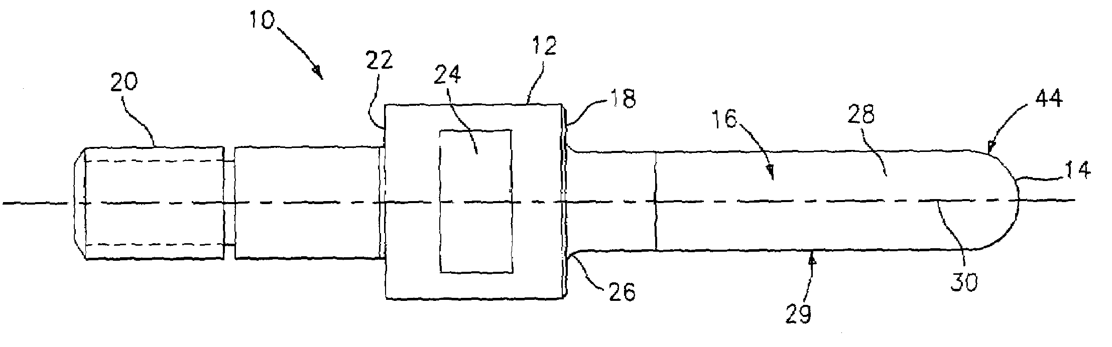
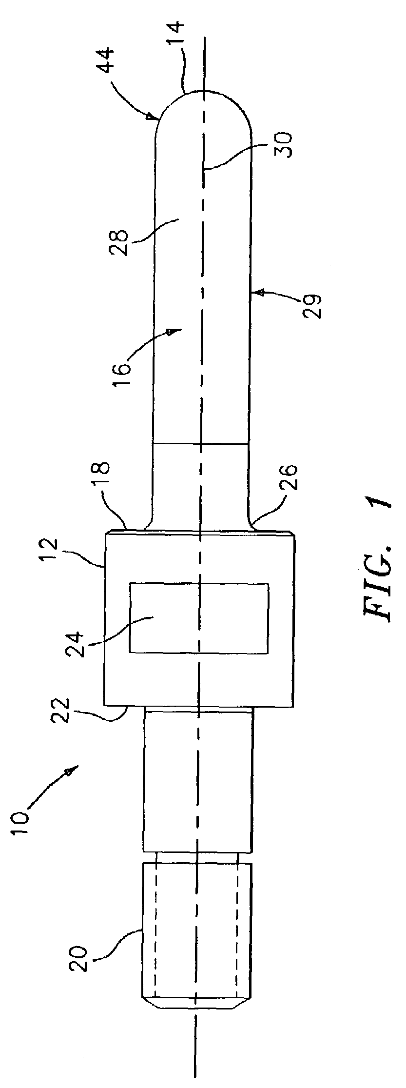
[0013]The present invention relates to point superabrasive machining. In this technique, a grinding tool coated with superabrasive grit is rotated at high RPMs to grind off the material.

[0014]Referring now to FIG. 1, a tool 10 for use in a point superabrasive machining process is illustrated. The tool 10 has an enlarged portion 12, a tip portion 14, and a first shaft portion 16 extending from a first surface 18 of the enlarged portion 12 to the tip portion 14. The tool 10 also has a second shaft portion 20 extending from a second surface 22 of the enlarged portion. The second shaft portion 20 fits into the grinding spindle of a high speed spindle on a machining center machine (not shown).

[0015]The tool 10, and in particular the first shaft portion 16, the second shaft portion 20, the enlarged portion 12, and the tip portion 14 may be formed from any suitable tool material known in the art, preferably a steel material. As can be seen from FIG. 1, the enlarged portion 12 has flattene...


PUM

PropertyMeasurementUnit
Diameteraaaaaaaaaa
Speedaaaaaaaaaa
Abrasiveaaaaaaaaaa

Abstract

A process for point superabrasive machining of a nickel based material comprising the steps of providing a tool having a grinding surface coated with a superabrasive material, orienting the tool relative to a surface of the nickel based material to be machined so that there is point contact between the surface to be machined and the grinding surface, and forming a part by removing material at the point contract by rotating the tool. The tool comprises an enlarged portion, a tip portion, and a first shaft portion extending from the enlarged portion to the tip portion, the first shaft portion and the tip portion being coated with an abrasive material, and the first shaft portion having a constant diameter.

Description

U.S. GOVERNMENT RIGHTS[0001]The Government may have rights in this invention, pursuant to Contract No. N00019-02-C-3003, awarded by the United States Navy.BACKGROUND OF THE INVENTION[0002]The present invention relates to a process for point superabrasive machining of nickel alloys and to a tool used in the process.[0003]Machining of complex shapes in nickel materials is typically performed using point milling. This technology uses a rotary multi-tooth cutter to remove material. Other more restrictive methods, such as electrochemical machining and flank milling, allow fast machining times but restrict the geometries that can be designed. Because of these restrictions, point milling is often used. This gives the designer maximum flexibility in component design. Point milling however is a relatively slow process when machining high hardness materials such as nickel alloys.SUMMARY OF THE INVENTION[0004]Accordingly, it is an object of the present invention to provide a process for point ...

Claims


Application Information

Patent Timeline
IPC IPC(8): B24B1/00B24B7/19B24B7/30B24B9/02B24B19/14B24B35/00B24D3/00B24D7/18B24D99/00
CPCB24B35/00B24D7/18E05B19/0082E05B47/00E05B2047/0084
Inventor SCHWARTZ, BRIAN J.GRADY, DANIEL F.WRIGHT, DANIEL J.
Owner RAYTHEON TECH CORP
Why Eureka
Try Eureka