Method for in-situ cleaning of carbon contaminated surfaces

a technology for cleaning apparatus and carbon contaminated surfaces, applied in the direction of photomechanical apparatus, cleaning using liquids, instruments, etc., can solve the problems of reduced efficiency, carbon contamination of multi-layer optics and masks, and inability to completely remove carbon

Inactive Publication Date: 2006-12-12
EUV
View PDF9 Cites 14 Cited by
  • Summary
  • Abstract
  • Description
  • Claims
  • Application Information

AI Technical Summary

Problems solved by technology

Some of the current sources of EUV eject debris that tend to coat optics used in photolithography which ultimately reduces efficiency.
In the next-generation of Extreme Ultraviolet Lithography (EUVL), multilayer based optics and masks will also be subject to carbon contamination.
Although contamination may be minimized by cleaning the vacuum environment, the carbon cannot be entirely removed.
One challenge in EUVL is that the optics will be buried under layers of surrounding hardware, such as mechanical frames and cabling, as well as mechanical devices used to perform and monitor the lithographic process.
The obscuring structures in the machine make it very difficult to direct reactive species generated from the exterior at the tool periphery to the optics located in the interior of the machine.

Method used


Image

  • Method for in-situ cleaning of carbon contaminated surfaces
  • Method for in-situ cleaning of carbon contaminated surfaces
  • Method for in-situ cleaning of carbon contaminated surfaces

Examples


Embodiment Construction

[0019]It is known that low energy electrons (about 0–50 eV) can activate gas phase molecules to make them more reactive than their ground (or unexcited) state. For example, oxygen and carbon dioxide can be electron activated at pressures of about 50–400 mTorr to form reactive gas-phase species (O2* and CO2*) which can be employed to gasify carbon in reactions that are represented as follows:

C+O2*=CO2(g)  (1)

C+CO2*=2CO(g)  (2)

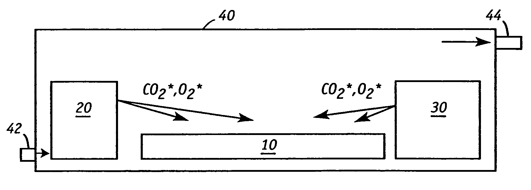
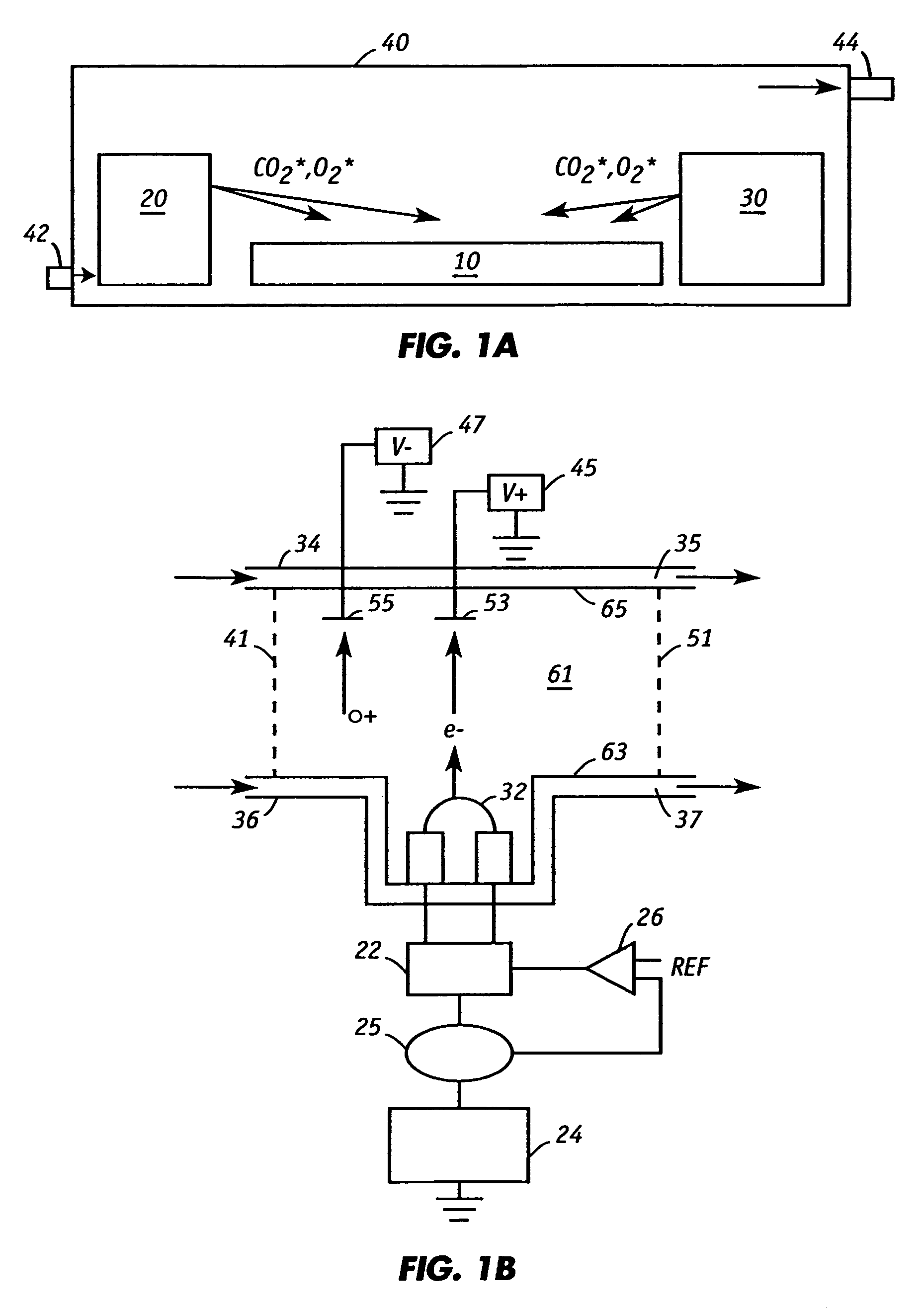
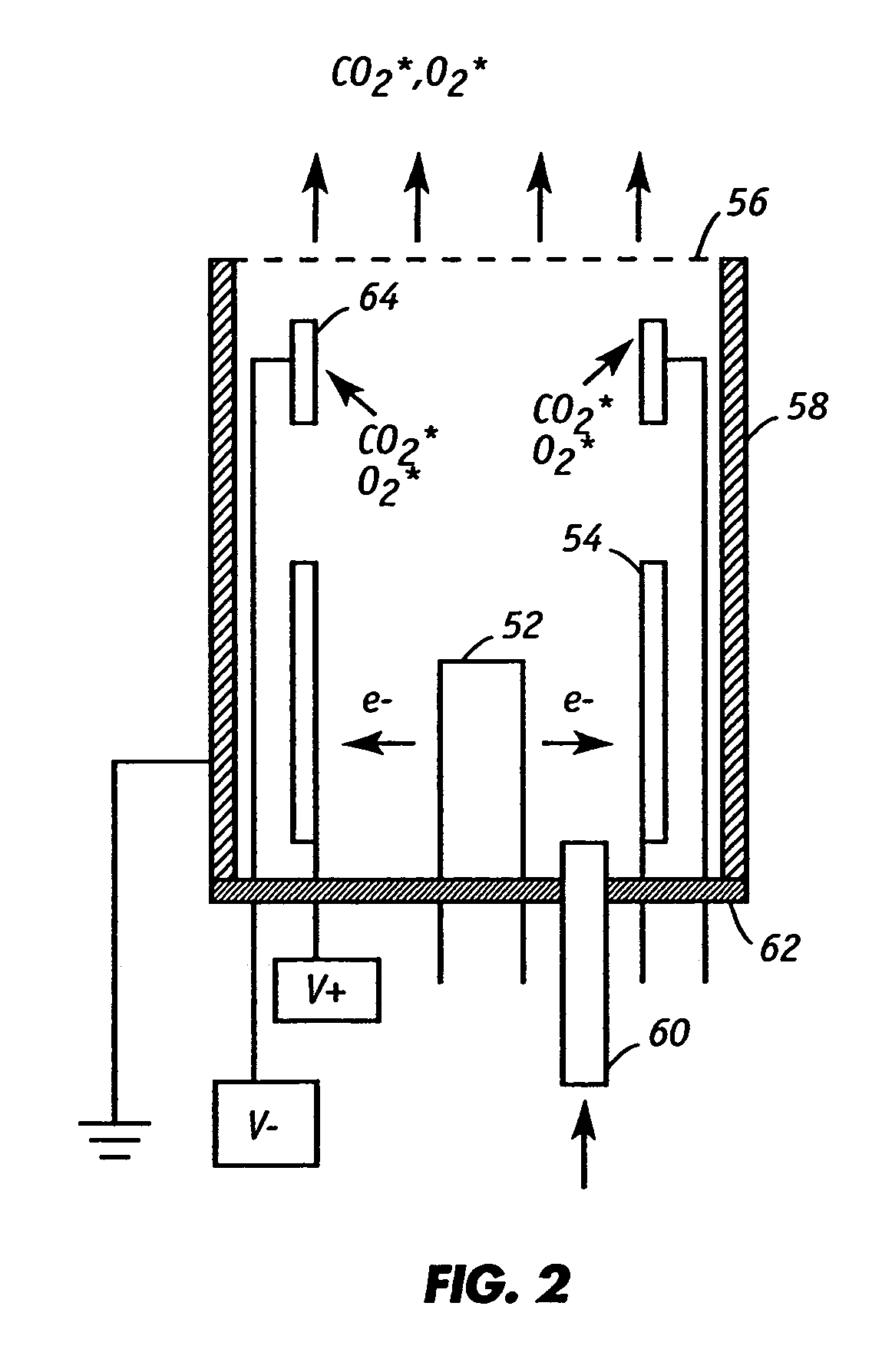
[0020]The present invention generates electron-activated gas phase species such as O2*, CO2* strategically inside the lithographic environment near the optics to remove carbon contaminants.

[0021]FIG. 1A illustrates one embodiment of the invention for in-situ cleaning of a carbon contaminated optic 10 (e.g., mirror that reflects extreme ultraviolet radiation) that is situated within a vacuum chamber defined by housing 40 of a photolithography machine. Located on opposite sides of the mirror are gas activation devices 20 and 30 that generate electron-activated gas...


PUM

PropertyMeasurementUnit
pressureaaaaaaaaaa
energyaaaaaaaaaa
wavelength rangeaaaaaaaaaa

Abstract

Activated gaseous species generated adjacent a carbon contaminated surface affords in-situ cleaning. A device for removing carbon contamination from a surface of the substrate includes (a) a housing defining a vacuum chamber in which the substrate is located; (b) a source of gaseous species; and (c) a source of electrons that are emitted to activate the gaseous species into activated gaseous species. The source of electrons preferably includes (i) a filament made of a material that generates thermionic electron emissions; (ii) a source of energy that is connected to the filament; and (iii) an electrode to which the emitted electrons are attracted. The device is particularly suited for photolithography systems with optic surfaces, e.g., mirrors, that are otherwise inaccessible unless the system is dismantled. A method of removing carbon contaminants from a substrate surface that is housed within a vacuum chamber is also disclosed. The method employs activated gaseous species that react with the carbon contaminants to form carbon containing gaseous byproducts.

Description

[0001]This application is a divisional application of U.S. Patent Application Publication No. 2003 / 0051739, published Mar. 20, 2003 now U.S. Pat. No. 6,772,776.[0002]This invention was made with Government support under Contract No. DE-AC04-94AL85000 awarded by the U.S. Department of Energy to Sandia Corporation. The Government has certain rights to the invention.FIELD OF THE INVENTION[0003]This invention relates generally to an apparatus for cleaning surfaces and particularly for cleaning optics by electron-activated gas-phase species.BACKGROUND OF THE INVENTION[0004]The present state-of-the-art for Very Large Scale Integration (“VLSI”) involves chips with circuitry built to design rules of 0.25 μm. Effort directed to further miniaturization takes the initial form of more fully utilizing the resolution capability of presently-used ultraviolet (“UV”) delineating radiation. “Deep UV” (wavelength range of λ=0.3 μm to 0.1 μm), with techniques such as phase masking, off-axis illuminatio...

Claims


Application Information

Patent Timeline
Patent Type & Authority Patents(United States)
IPC IPC(8): B08B3/12B08B6/00B08B7/00G03F7/20
CPCB08B7/0035G03F7/70925H01J2237/3151Y10S134/902
Inventor KLEBANOFF, LEONARD E.GRUNOW, PHILIPGRAHAM, JR., SAMUEL
Owner EUV
Why Eureka
Try Eureka