Method and apparatus for duct sealing using a clog-resistant insertable injector

a technology of insertable injectors and duct sealing, which is applied in the direction of lighting and heating apparatus, combustion types, heating types, etc., can solve the problems of reducing the availability of downstream sealant particles, frequent clogging, and narrow ducts limiting the application of duct sealing applications

Active Publication Date: 2007-01-02
RGT UNIV OF CALIFORNIA
View PDF21 Cites 11 Cited by
  • Summary
  • Abstract
  • Description
  • Claims
  • Application Information

AI Technical Summary

Benefits of technology

[0052]The innermost liquid tube is preferably cylindrical, but other shapes may be employed. The inner hollow member is also preferably cylindrical, and is referred to below as an “inner cylinder.” The outermost propellant cap provides a receiving chamber for heated propellant gas. The heated propellant gas is prevented from heating the liquid by a thermally insulating space, which may be flowing air or other insulating material, as described above. This thermally insulating space is alternatively known as the heat transfer region. The air flows into and out of the nozzle by a venturi effect created by the spray.

Problems solved by technology

These prior nozzles variously suffered from frequent clogging and / or a particulate spray cone angle too wide for direct injection within narrow ducts.
Narrow ducts form a limiting application for duct sealing applications.
Counter-rotating vortex nozzles do not appear to have serious clogging problems, however they create large spray angles and require considerable dilution (e.g. nine parts liquid to one part solid) to make particles in a size range suitable for sealing ducts.
Such large spray cone angles are unusable for sealing narrow ducts, as a large fraction of the overall spray output is immediately coated on the sides of the narrow duct, thereby reducing the availability of downstream sealant particles and thereby increasing sealing time.
When the propellant gas is heated, preferably forming simple heated compressed air, clogging within the atomizer is increased.
Diluting the sealant poses two problems.
Thus, dilution increases the heat requirements per unit mass of desolvated sealant delivered.
Another disadvantage found in current embodiments of both the '930 and '984 patents is the requirement that the ducts be connected to an external fan and spray apparatus, which may be difficult to install, and intrusive in inhabited buildings.
In these situations, considerable time and expense may be required simply to gain access to the ducts and isolate the HVAC equipment from the aerosol particles.
In most homes, there is insufficient head produced to allow effective duct sealing, and an additional fan must be placed in series with, and in addition to, the originally installed fan in order to raise the head sufficiently to seal the ducts.
Nearly all fan systems have doors for fan access, however the atomizers used by the earlier inventions for duct sealing applications did not allow use of those access doors to connect the external fan, as the aerosol particles were created right at the external fan, and would be blown through the fan and HVAC equipment, thereby unacceptably coating the equipment with sealant.

Method used


Image

  • Method and apparatus for duct sealing using a clog-resistant insertable injector
  • Method and apparatus for duct sealing using a clog-resistant insertable injector
  • Method and apparatus for duct sealing using a clog-resistant insertable injector

Examples


Embodiment Construction

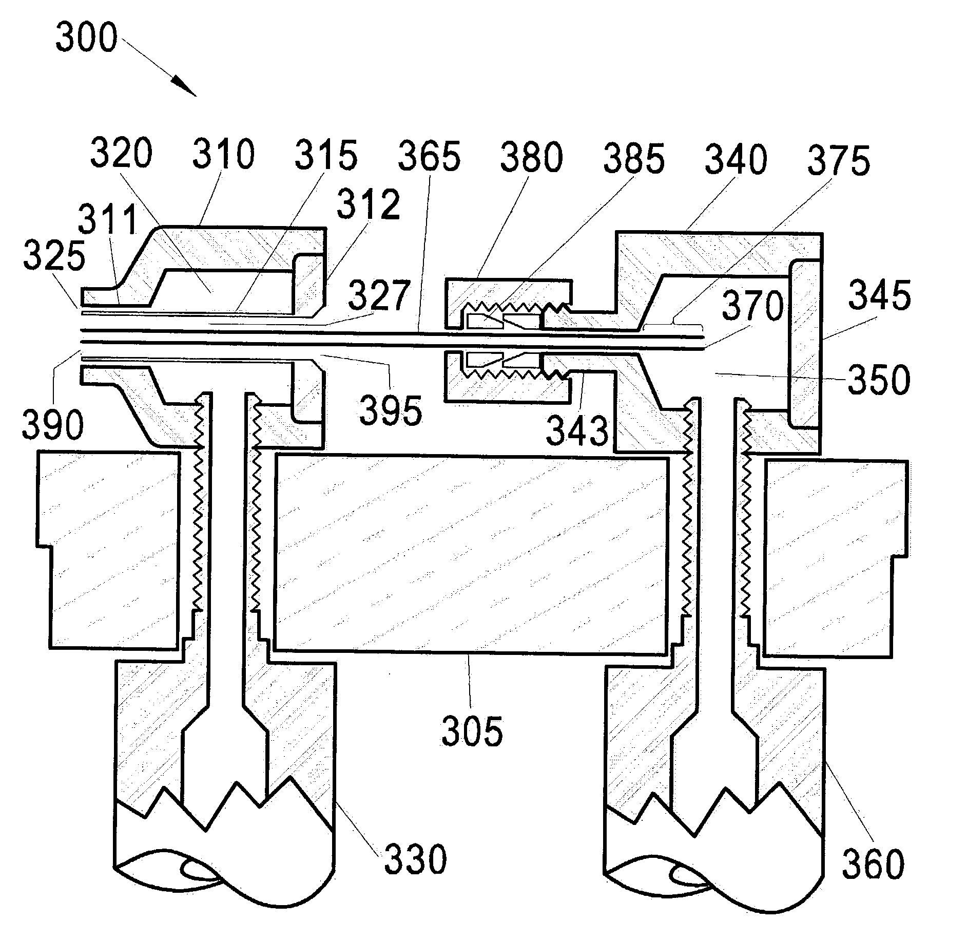
[0064]In general, the present compact aerosol sealant injector provides nebulization or atomization of a pressurized liquid supply at a location near the nozzle tip. When the liquid supply is ejected in close proximity to the propellant, turbulent mixing occurs, forming a fine liquid mist, or liquid spray. The turbulent mixing phenomenon is extremely complex, depending on variables such as: relative flow velocities, densities, viscosities, surface tensions, and temperature distributions, etc., in both flows. Further representative references regarding the physics and fluid dynamics of atomizers and sprayers, incorporated herein by reference, are: Atomization and Sprays, by Arthur H. Lefebvre, Hemisphere Publishing Company, 1978; and Liquid Atomization, by L. Bayvel and Z. Orzewchowski, Taylor & Francis, 1993. This phenomenon becomes yet more complex when a heated propellant gas is used to desolvate or dry particles in the liquid supply.

[0065]Heating the propellant gas has many advan...


PUM

PropertyMeasurementUnit
cone angleaaaaaaaaaa

Abstract

A clog-resistant injector spray nozzle allows relatively unobtrusive insertion through a small access aperture into existing ductwork in occupied buildings for atomized particulate sealing of a ductwork. The spray nozzle comprises an easily cleaned and easily replaced straight liquid tube whose liquid contents are principally propelled by a heated propellant gas, such as heated air. Heat transfer is minimized from the heated propellant gas to the liquid tube until they both exit the injector, thereby greatly reducing the likelihood of nozzle clogging. A method of duct sealing using particles driven by heated propellant gas is described, whereby duct-sealing operations become both faster, and commercially practicable in inhabited commercial and residential buildings.

Description

CROSS REFERENCE TO RELATED APPLICATIONS[0001]This application claims priority to U.S. provisional patent application Ser. No. 60 / 338,562 filed Dec. 3, 2001, entitled “Compact aerosol-sealant injector system,” hereby incorporated by reference.STATEMENT REGARDING FEDERAL FUNDING[0002]This invention was made with U.S. Government support under Contract Number DE-AC03-76SF00098 between the U.S. Department of Energy and The Regents of the University of California for the management and operation of the Lawrence Berkeley National Laboratory. The U.S. Government has certain rights in this invention.REFERENCE TO A COMPUTER PROGRAM[0003]Not Applicable.BACKGROUND OF THE INVENTION[0004]1. Field of the Invention[0005]The present invention pertains generally to atomization and drying of liquids, particularly liquids that have a propensity to clog atomization devices, examples include, but are not limited to adhesives, sealants, coatings, and paint. The present invention pertains particularly to d...

Claims


Application Information

Patent Timeline
Patent Type & Authority Patents(United States)
IPC IPC(8): B05B1/24B05B7/06B05B7/00B05B7/16B05D7/22F16L55/164
CPCB05B7/0087B05B7/066B05D7/222F16L55/164B05B7/1626B05B7/0075F24F2006/143
Inventor WANG, DUOMODERA, MARK P.
Owner RGT UNIV OF CALIFORNIA
Why Eureka
Try Eureka