X-ray diffraction apparatus

Active Publication Date: 2007-01-02
RIGAKU CORP
View PDF14 Cites 14 Cited by
  • Summary
  • Abstract
  • Description
  • Claims
  • Application Information

AI Technical Summary

Benefits of technology

[0022]Thus, the present invention provides an X-ray apparatus which is largely pre-aligned and fixed in an integrated unit during manufacture. Subsequent adjustment and optimisation of the alignment can be performed in a simple, step-by-step manner. The compact natu

Problems solved by technology

The known system is difficult to adjust accurately and reliably, due to the large nu

Method used


Image

  • X-ray diffraction apparatus
  • X-ray diffraction apparatus
  • X-ray diffraction apparatus

Examples


Embodiment Construction

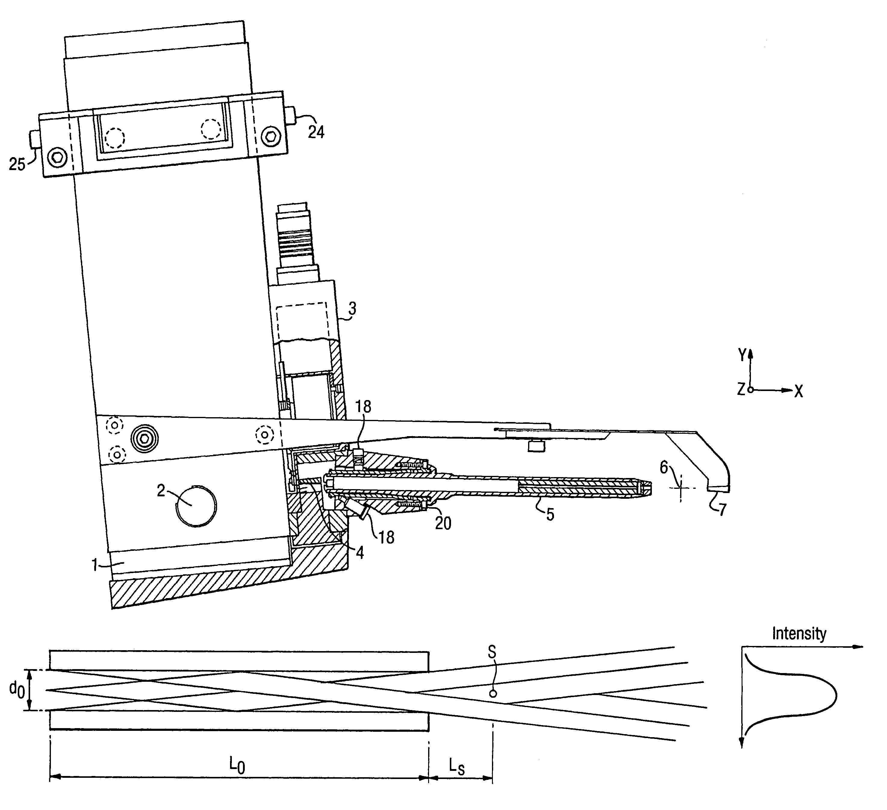
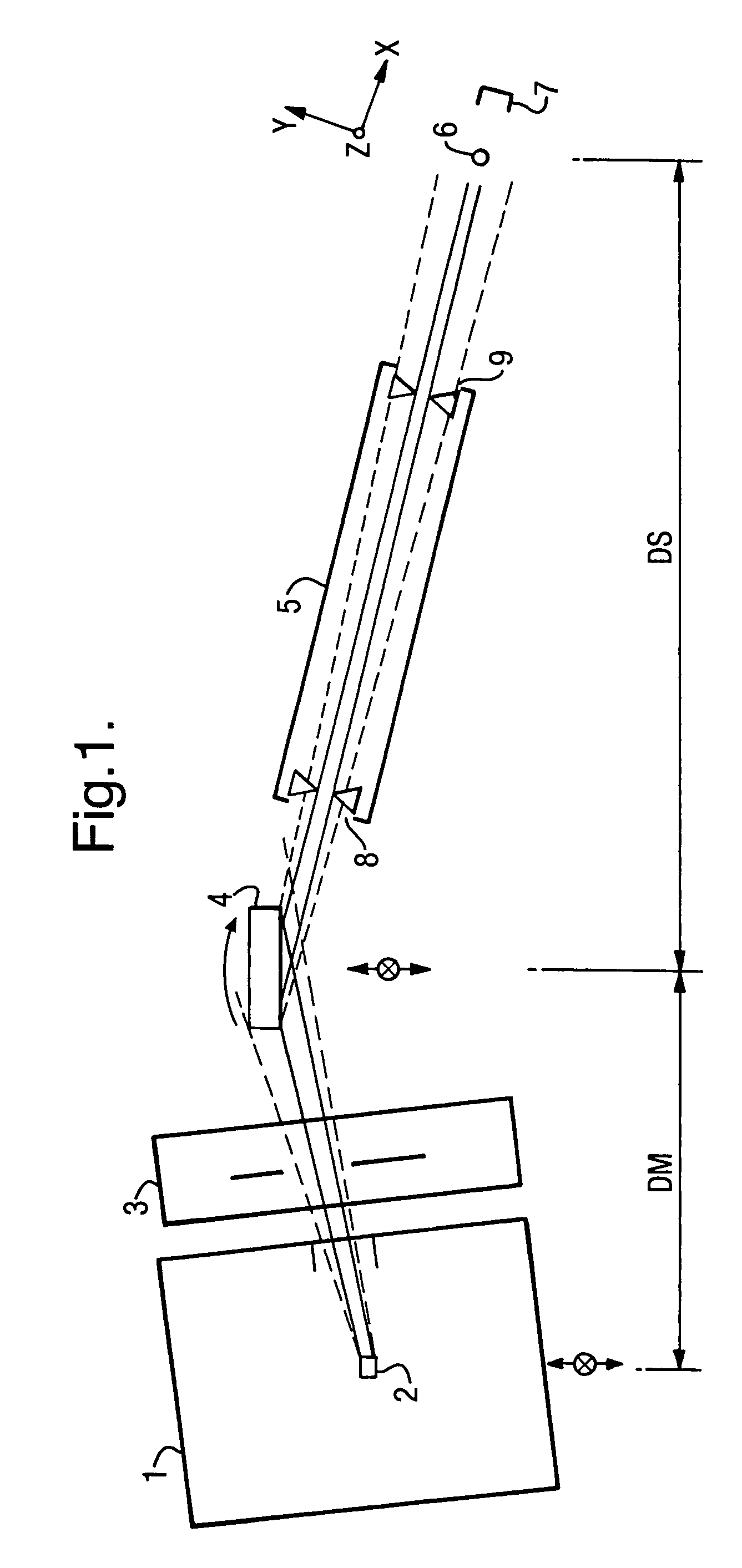
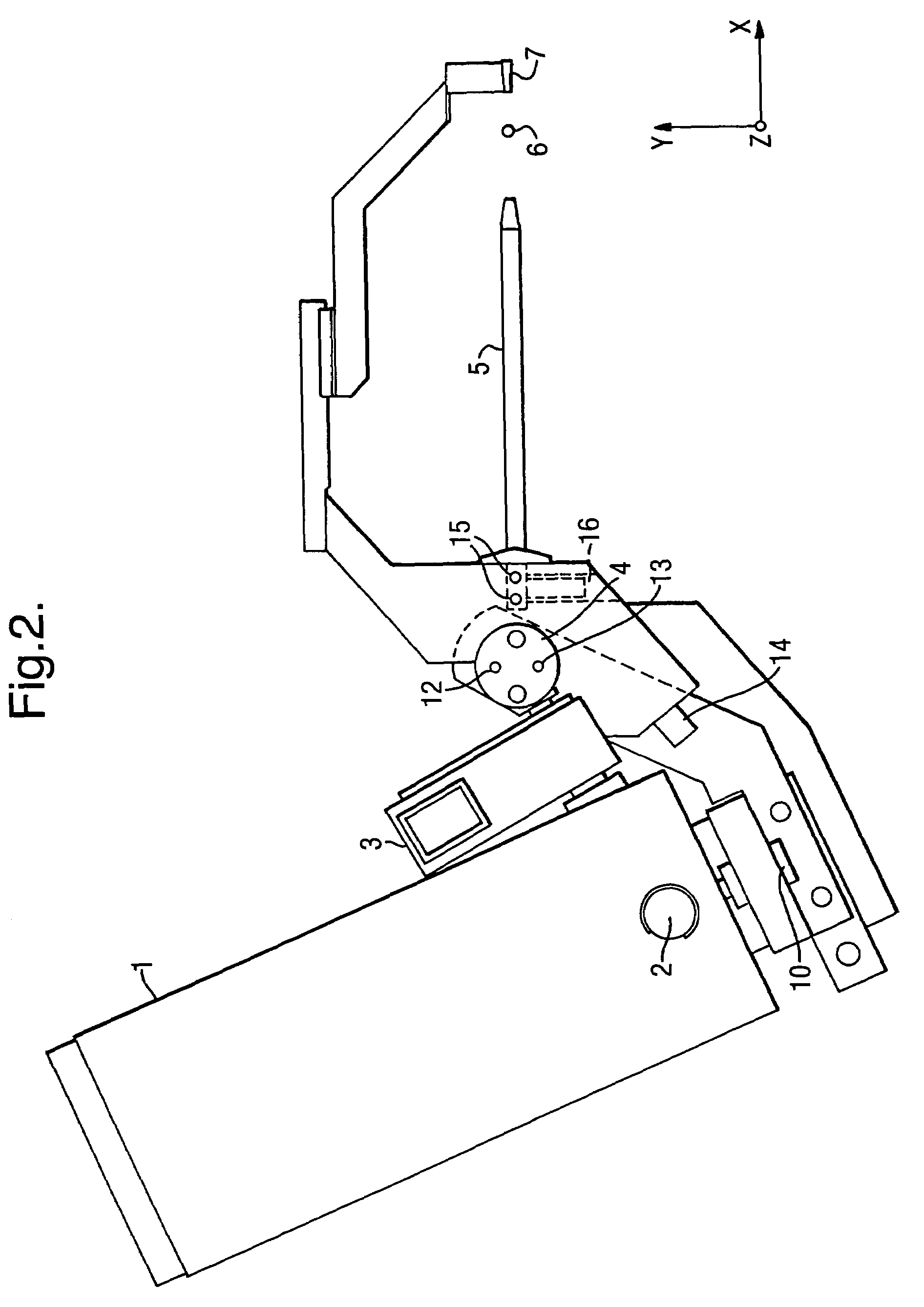
[0038]FIGS. 1 and 2 illustrate a prior art arrangement of x-ray optics components. The arrangement includes an x-ray source 1 which emits an x-ray beam from a focal spot 2; a shutter 3 for isolating the source; a monochromator 4 for generating a monochromatic x-ray beam from the incident beam generated by the source 1; a collimator 5 arranged to collimate the beam from the monochromator 4 onto a sample 6; and a beam stop 7.

[0039]The x-ray source 1 is a sealed tube inducing an electron gun and a target such as molybdenum or copper which generates x-rays when bombarded with electrons from the electron gun. The x-ray source 1 generates an x-ray beam from focal spot 2, which passes through the shutter 3 and is reflected from the monochromator 4 as a monochromatic beam, which enters the collimator 5 and is directed onto the sample 6. The collimator 5 is a standard pin hole type collimator having an entry pin hole 8 and an exit pin hole 9. The amount of flux which is lost due to divergenc...


PUM


Abstract

An x-ray diffraction apparatus comprises an x-ray source for generating an x-ray beam, a monochromator for generating a monochromatic x-ray beam from the x-ray beam, and a collimator for collimating the monochromatic x-ray beam and directing it onto a sample, wherein the x-ray source and the monochromator are pre-assembled and fixed with respect to each other in an integrated unit such that in use the path length of the x-ray beam from the source to the monochromator is maintained substantially constant. X-ray flux at the sample is further enhanced by use of a partial monocapillary collimator arranged to direct part of the X-ray beam to the sample by a single grazing reflection.

Description

FIELD OF THE INVENTION[0001]X-ray diffraction is an analytical technique for obtaining information on the structure of atoms or molecules in a crystal from the diffraction pattern which is produced by diffraction of x-rays by the crystal's atomic planes. The present invention concerns an improved apparatus for x-ray diffraction, and particularly an improved optics set up for increasing the maximum flux which can be obtained from an x-ray source.BACKGROUND TO THE INVENTION[0002]An x-ray diffraction apparatus typically includes an x-ray source which comprises a sealed tube including an electron gun and a target such as molybdenum or copper which generates x-rays when bombarded with electrons from the electron gun. The x-rays emerge from a pin hole in the sealed source unit, and a separate shutter unit is generally located adjacent the source unit to isolate the source unit when necessary for safety reasons. The shutter unit is located between the source and a monochromator. The x-ray ...

Claims


Application Information

Patent Timeline
IPC IPC(8): G01N23/20G21K1/06
CPCG21K1/06G01N23/20
Inventor KUCHARCZYK, DAMIAN
Owner RIGAKU CORP
Why Eureka
Try Eureka