Method and apparatus for enhancing the integrity of an implantable sensor device

a sensor device and integrity technology, applied in the field of medical devices, can solve the problems of unstable sensing performance or sensor failure, oxygen sensor implanted into the body, requiring frequent and periodic recalibration and replacement, etc., and achieves the effect of reducing the size of the window opening, minimizing the window perimeter, and reducing flux

Inactive Publication Date: 2007-01-09
MEDTRONIC MIMIMED INC
View PDF18 Cites 169 Cited by
  • Summary
  • Abstract
  • Description
  • Claims
  • Application Information

AI Technical Summary

Benefits of technology

[0017]In one or more embodiments, spatial voids between the outer tubing and the internal elements of the sensor module may be back-filled to inhibit diffusion of unwanted fluids within the sensor device. In one or more embodiments, the back-fill material may be, for example, a curable, implantable material, such as, for example, silicone, epoxy, bone cement, foam or the like.
[0018]In one or more embodiments, the size of the window opening may be reduced to minimize the window perimeter that is subject to stress and wear, as well as to reduce the flux and thus extend the useful life of the enzyme or protein matrix. The size of the underlying electrode may also be reduced by controlling the processes used to form the electrode.
[0019]In one or more embodiments of the invention, the enzyme or protein matrix may be a pre-treated enzyme or protein matrix pellet, washed with a reducing agent to prevent excessive swelling. The reducing agent may be, for example, Ascorbate. As a result, the enzyme or protein matrix pellet may be less prone to destabilization and less likely to cause detachment of the overlying hydrogel layer.

Problems solved by technology

Nonetheless, challenges in the biosensing field have remained.
For example, although many diabetics currently utilize diagnostic medical equipment in the comfort of their own homes, the vast majority of such devices still require diabetics to draw their own blood and inject their own insulin.
Unfortunately, oxygen sensors implanted into the body have, thus far, typically required frequent and periodic recalibration and replacement.
When the integrity of the sensor structure fails, either partially or completely, undesired fluids and cells may diffuse into the sensor structure, causing unstable sensing performance or sensor failure.
For example, once the integrity of an implanted sensor has become compromised, blood may pool and clot around electrodes, fibrous growths may develop over the top of electrodes, and softer elements (e.g., enzymes, protein matrices, membranes and the like) of the sensor may deteriorate or be digested.
These surgical procedures are semi-invasive, expensive and inconvenient.
Further, unless the sensor fails completely, it may be difficult to detect the exact status of the sensor without explanting it first.
In clinical experiments, complications have arisen during implantation of a sensor due to the flexibility of the sensor structure.
A surgeon may find that the sensor lead buckles under the axial pressure exerted by the surgeon to force the sensor through the introducer, particularly if a kink is formed in the introducer.
As a result of buckling, the sensor may be damaged.
As a result of the insufficient stiffness of the sensor lead 150, it may hang in a flaccid state when gripped in this manner, making it difficult to place into the introducer.
However, while gripping the sensor lead 150 in this manner, the surgeon may inadvertently damage the sensor, for example, by exerting excessive pressure on the sensor or because the sensor is made from fragile materials.
This may result in a reduction in the accuracy of the sensor readings or may cause vessel irritation.

Method used


Image

  • Method and apparatus for enhancing the integrity of an implantable sensor device
  • Method and apparatus for enhancing the integrity of an implantable sensor device
  • Method and apparatus for enhancing the integrity of an implantable sensor device

Examples


Embodiment Construction

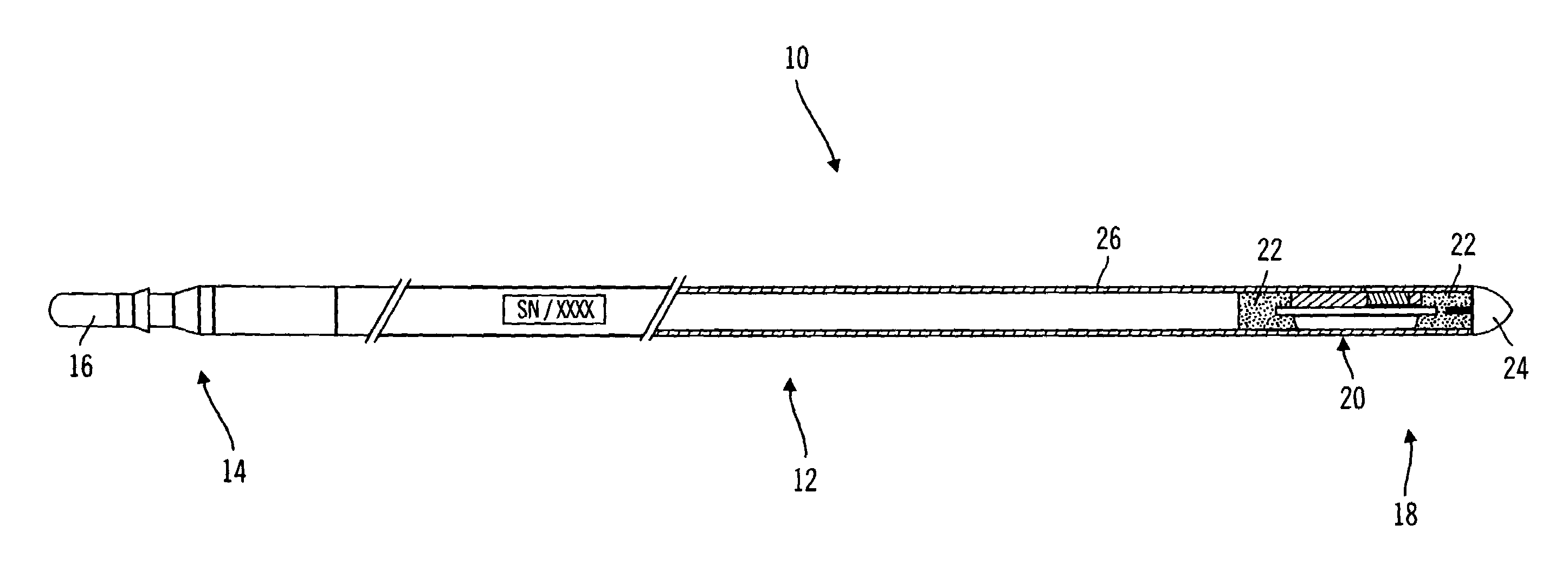
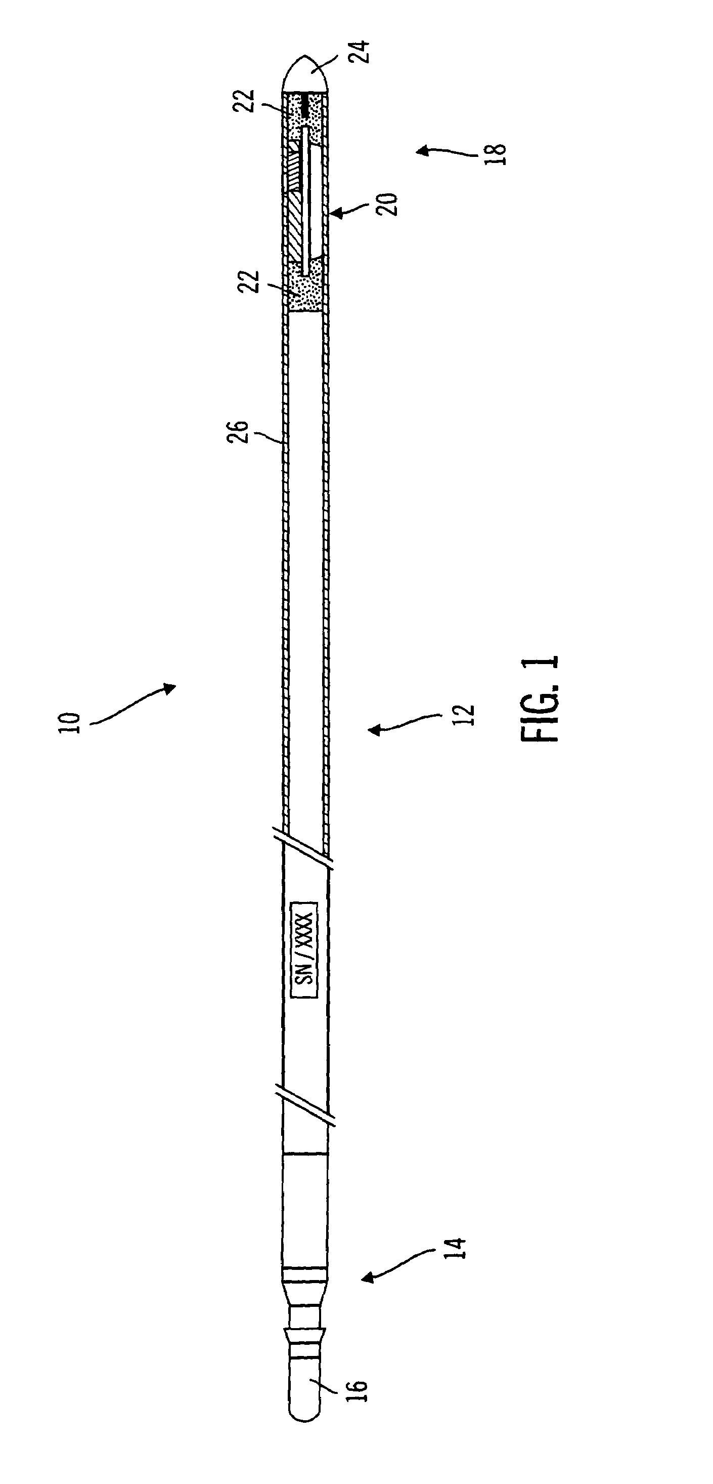
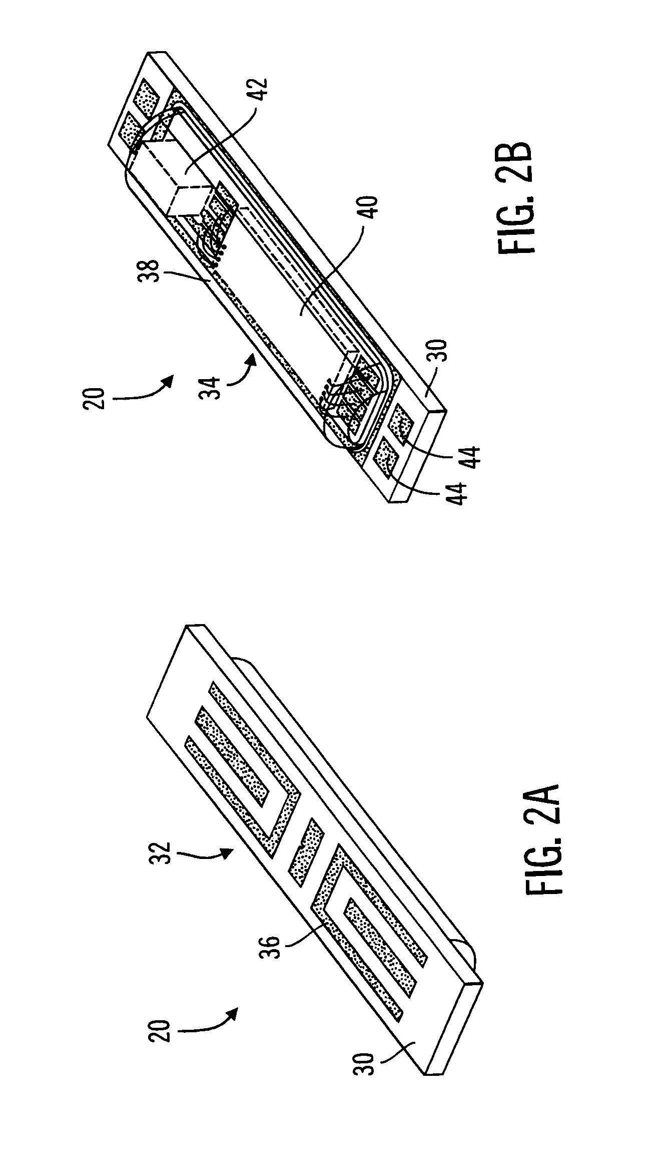
[0045]The present invention relates generally to sensor structures for electronic medical implant devices, and to methods for making such sensors. This description is not to be taken in a limiting sense, but is made merely for the purpose of illustrating the general principles of example embodiments of the invention. The scope of the invention is best defined by the appended claims. In the following description, numerous specific details are set forth to provide a more thorough description of one or more embodiments of the invention. It will be apparent, however, to one skilled in the art, that the invention may be practiced without these specific details. Other embodiments may be utilized and structural changes may be made without departing from the scope of the present invention. Though described herein as a sensor for monitoring physiological parameters such as glucose level, for example, it will be apparent that embodiments of the invention are also applicable to other sensor ap...


PUM

PropertyMeasurementUnit
swellingaaaaaaaaaa
elastomericaaaaaaaaaa
flexibilityaaaaaaaaaa

Abstract

A method and apparatus for enhancing the integrity of an implantable sensor. Voids formed between an outer tubing and a sensor substrate or spacing element may be back-filled with a curable, implantable material, minimizing the extent to which unwanted fluids diffuse within the sensor. An enzyme or protein matrix pellet below the sensor window may be pre-treated with a reducing agent to enhance its bond stability, and to reduce undesired swelling that may cause the sensor window to detach or leak. The bonding between the enzyme pellet and a hydrogel layer may be reinforced by application of an intervening bonding layer of a protein material, such as human serum albumin (HSA). The size of the window may be minimized by minimizing the size of an underlying electrode, providing reduced flux and lengthening sensor. A coating may be deposited on the surface of the sensor leads, providing stiffening and lubrication.

Description

CROSS-REFERENCE TO RELATED APPLICATIONS[0001]Embodiments of the present invention relate to U.S. Provisional Application Ser. No. 60 / 414,142, filed Sep. 27, 2002, entitled “Method and Apparatus for Enhancing the Integrity of an Implantable Sensor Device,” which is incorporated by reference herein and is a basis for a claim of priority.BACKGROUND[0002]1. Field of the Invention[0003]The present invention relates generally to the field of medical devices, and, more specifically, to sensor structures for medical implants.[0004]2. Related Art[0005]The combination of biosensors and microelectronics has resulted in the availability of portable diagnostic medical equipment that has improved the quality of life for countless people. Many people suffering from disease or disability who, in the past, were forced to make routine visits to a hospital or doctor's office for diagnostic testing currently perform diagnostic testing on themselves in the comfort of their own homes using equipment with...

Claims


Application Information

Patent Timeline
Patent Type & Authority Patents(United States)
IPC IPC(8): A61B5/00A61B5/05C12M1/00C12Q1/00
CPCA61B5/14532A61B5/14865A61B5/686G01N33/5438A61B2562/02Y10T29/49007Y10T29/49128Y10T29/49155Y10T29/49002
Inventor SHAH, RAJIVZHANG, YANANGOTTLIEB, REBECCAREGHABI, BAHARMILLER, MICHAEL
Owner MEDTRONIC MIMIMED INC
Why Eureka
Try Eureka