Fuel injection system and method

Active Publication Date: 2007-01-16
FORD GLOBAL TECH LLC
View PDF17 Cites 21 Cited by
  • Summary
  • Abstract
  • Description
  • Claims
  • Application Information

AI Technical Summary

Benefits of technology

[0001]Engines utilize various types of fuel injection adjustments to provide improved engine performance. One example fuel injection compensation methods increases or decreases fuel injection to account for fuel adhered to walls of the intake manifold, intake valves, and/or intake ports. Such phenomena may be referred to as wall wetting dynamics, or tran

Problems solved by technology

Second, the inventors herein have also recognized that the determination

Method used


Image

  • Fuel injection system and method
  • Fuel injection system and method
  • Fuel injection system and method

Examples


Embodiment Construction

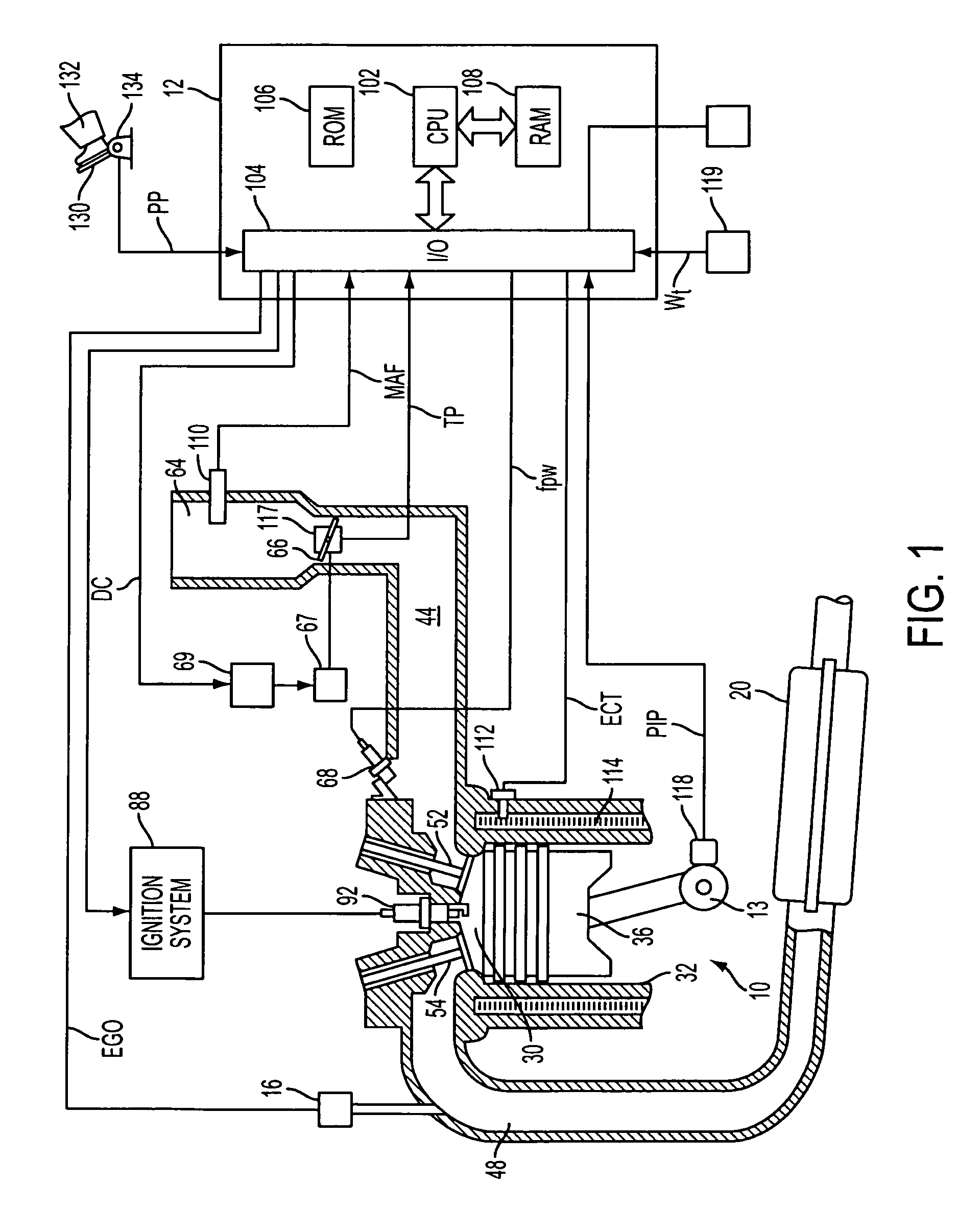
[0007]Internal combustion engine 10 comprising a plurality of cylinders, one cylinder of which is shown in FIG. 1, is controlled by electronic engine controller 12. Engine 10 includes combustion chamber 30 and cylinder walls 32 with piston 36 positioned therein and connected to crankshaft 13. Combustion chamber 30 communicates with intake manifold 44 and exhaust manifold 48 via respective intake valve 52 and exhaust valve 54. Exhaust gas oxygen sensor 16 is coupled to exhaust manifold 48 of engine 10 upstream of catalytic converter 20.

[0008]Intake manifold 44 communicates with throttle body 64 via throttle plate 66. Throttle plate 66 is controlled by electric motor 67, which receives a signal from ETC driver 69. ETC driver 69 receives control signal (DC) from controller 12. Intake manifold 44 is also shown having fuel injector 68 coupled thereto for delivering fuel in proportion to the pulse width of signal (fpw) from controller 12. Fuel is delivered to fuel injector 68 by a convent...


PUM


Abstract

A method for adjusting fuel injection, the method comprising during an engine start from a non-warmed-up condition, identifying a fuel quality of fuel supplied to the engine during said start based on a performance of said start, and after said start is completed and during a transient fueling condition, adjusting a fuel injection amount based on said identified fuel quality from said start.

Description

BACKGROUND AND SUMMARY[0001]Engines utilize various types of fuel injection adjustments to provide improved engine performance. One example fuel injection compensation methods increases or decreases fuel injection to account for fuel adhered to walls of the intake manifold, intake valves, and / or intake ports. Such phenomena may be referred to as wall wetting dynamics, or transient fuel dynamics. To compensate for such dynamics, the amount of fuel injected is varied to compensate for the fuel stored in the intake manifold and intake ports based on various models and estimates taking into account engine operating conditions. In this way, more accurate air / fuel ratio control may be achieved in of the combusted air / fuel mixture.[0002]One example of fuel injection control is described in U.S. Pat. No. 5,492,101. In this example, a transient fuel compensation is described that uses an atomized fuel behavioral model, intake passage fuel behavioral model, and a combustion fuel behavioral mo...

Claims


Application Information

Patent Timeline
IPC IPC(8): F02D41/06
CPCF02D41/064F02D41/1497F02D41/047F02D2200/0611F02D2200/0406
Inventor HALVERSON, JONZHANG, XIAOYINGWAGERS, SUELINENBERG, MARKSCANNELL, MIKE
Owner FORD GLOBAL TECH LLC
Why Eureka
Try Eureka