Reusable analyte sensor site and method of using the same

a technology of analyte sensor and reusable analyte, which is applied in the field of reusable analyte sensor sites, can solve the problems of requiring regular replacement, unable to provide continuous data, so as to promote vascularization

Inactive Publication Date: 2007-01-23
MEDTRONIC MIMIMED INC
View PDF17 Cites 402 Cited by
  • Summary
  • Abstract
  • Description
  • Claims
  • Application Information

AI Technical Summary

Benefits of technology

[0030]In still another embodiment of the present invention, a reusable infusion site for use with a replaceable catheter for infusing a fluid into a body of a patient includes a site housing and a resealable insertion site. The site housing is formed to have an interior cavity. Additionally, the site housing includes an outer membrane made of a material selected to promote vascularization and having a first pore size, and an inner membrane being made of a material selected to be free of tissue ingress and having a second pore size. The site housing also permits the fluid to pass out through the site housing from the interior cavity to deliver the fluid into the body of the patient. Further, the resealable insertion site is coupled to one end of the site housing for inserting the replaceable catheter into the interior cavity of the site housing.

Problems solved by technology

This results in discomfort from the lancet as it contacts nerves in the subcutaneous tissue.
In addition, these blood glucose meters are only designed to provide data at discrete points and do not provide continuous data to show the variations in the characteristic between testing times.
Also, due to the small size of this sensor to minimize pain on insertion under the skin, the enzymes on the sensor wear out relatively quickly and require regular replacement.
Thus, although subcutaneous sensors provide an improvement over conventional test strips, they still require frequent changes.
However, the long term glucose sensor is typically placed in the superior vena cava of the patient's body, and the insertion and placement of the long term sensor in this location is quite invasive to the body and requires much effort by an attending physician.
As a result, removal and replacement of long term sensors in the superior vena cava is difficult.
After insertion, the long term sensor would not be usable for a period of time until the body heals and vascularizes the implanted long term sensor.
Another drawback to long term sensors is the development of scar tissue at the insertion site that encapsulates the implanted sensor formed with the outer covering.
This requires careful construction of the outer covering for the long term sensor, which increases costs and may further delay the period of time before a newly implanted sensor may be used.
Further, extensive surgery may be required to cut through the scar tissue and remove the implanted sensor, thus rendering the insertion site unusable for implantation of a replacement sensor.

Method used


Image

  • Reusable analyte sensor site and method of using the same
  • Reusable analyte sensor site and method of using the same
  • Reusable analyte sensor site and method of using the same

Examples


Embodiment Construction

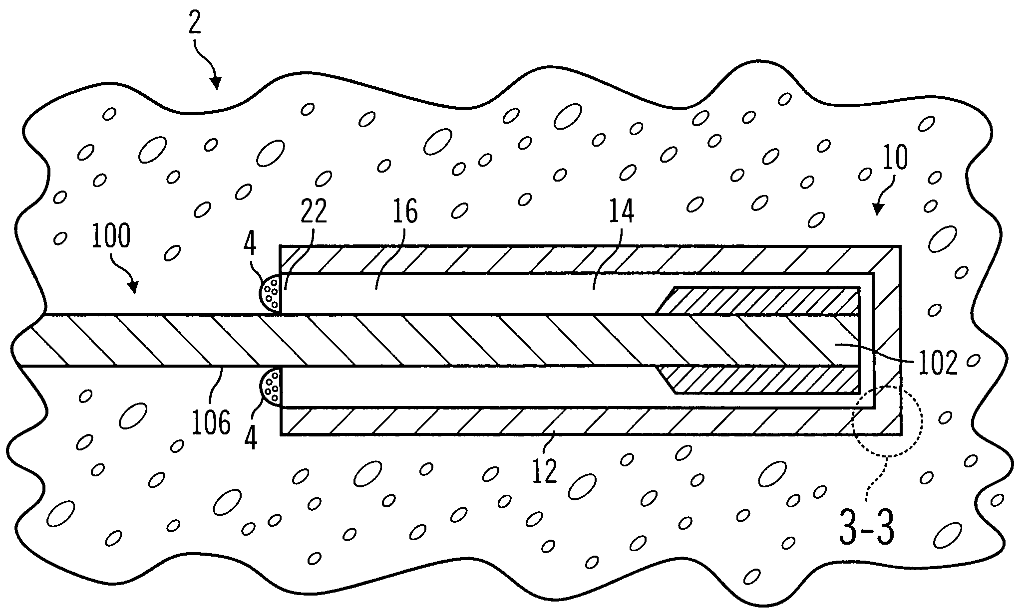
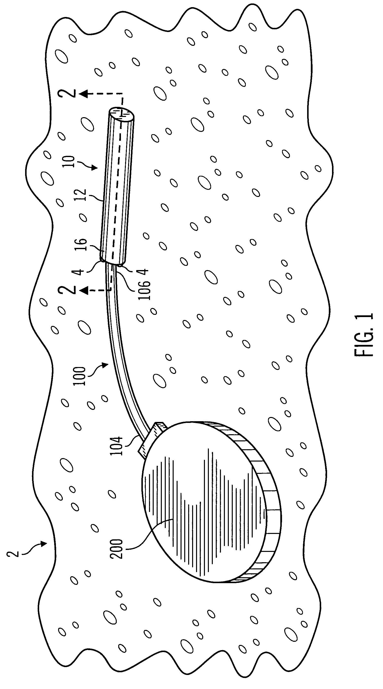
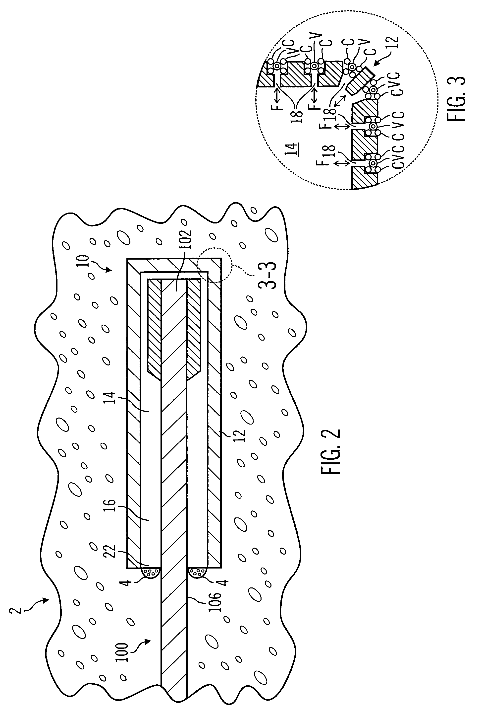
[0045]As shown in the drawings for purposes of illustration, the invention is embodied in a reusable analyte sensor site that is used with a replaceable analyte sensor that determines body characteristics on a continuous, intermittent or near continuous basis. In preferred embodiments of the present invention, the replaceable analyte sensor is for determining glucose levels in the blood and / or bodily fluids of the user. However, it will be recognized that further embodiments of the invention may be used to determine the levels of other agents, characteristics or compositions, such as lactate, oxygen, hormones, cholesterol, medication concentrations, viral loads (e.g., HIV), or the like. The reusable analyte sensor site and replaceable analyte sensor are primarily adapted for use in sub-dermal or inter-peritoneal human tissue. However, still further embodiments may be placed in other types of tissue, such as muscle, lymph, organ tissue, veins, arteries or the like, and used in animal...


PUM


Abstract

A reusable analyte sensor site for use with a replaceable analyte sensor for determining a level of an analyte includes a site housing and a resealable insertion site coupled to one end of the site housing. Preferably, the site housing is formed to have an interior cavity, and includes an outer membrane made of a material selected to promote vascularization and having a first pore size, and an inner membrane made of a material selected to be free of tissue ingress. Also, the site housing permits the analyte to pass through the site housing to the interior cavity to permit measurement by the replaceable analyte sensor. The resealable insertion site is provided for inserting the replaceable analyte sensor into the interior cavity of the site housing.

Description

RELATED APPLICATIONS[0001]This application is a continuation of U.S. patent application Ser. No. 10 / 365,279 filed Feb. 12, 2003 and entitled “Reusable Analyte Sensor Site and Method of Using the Same,” which is a continuation-in-part of U.S. patent application Ser. No. 10 / 028,070 filed Dec. 21, 2001 and entitled “Reusable Analyte Sensor Site and Method of Using the Same,” which is a divisional of U.S. patent application Ser. No. 09 / 566,027 filed May 8, 2000 and entitled “Reusable Analyte Sensor Site and Method of Using the Same,” now U.S. Pat. No. 6,368,274 issued Apr. 9, 2002, which claims priority on U.S. Provisional Application Ser. No. 60 / 141,935 filed Jul. 1, 1999 and entitled “Reusable Analyte Sensor Site and Method of Using the Same,” all of which are herein specifically incorporated by reference.FIELD OF THE INVENTION[0002]This invention relates to reusable analyte sensor sites for use with replaceable, long term implantable analyte sensors, infusion catheters, stimulators, ...

Claims


Application Information

Patent Timeline
Patent Type & Authority Patents(United States)
IPC IPC(8): A61B5/00A61B5/05A61M39/02
CPCA61B5/076A61B5/14503A61B5/14532A61B5/14546A61B5/1459A61B5/14865A61M39/0208
Inventor REGHABI, BAHARSHAH, RAJIVJIN, EUNJOOGOTTLIEB, REBECCAMILLER, MICHAEL E.VAN ANTWERP, NANNETTE M.ENEGREN, BRADLEY J.VAN ANTWERP, WILLIAM P.MASTROTOTARO, JOHN J.
Owner MEDTRONIC MIMIMED INC
Why Eureka
Try Eureka